Rockwell Automation Publication 750-IN001O-EN-P - October 2014 127
Lift and Mount the Drive Chapter 3
Release Cabinet Options
Assembly From Cabinet
To access the interior of the cabinet options cabinet to complete installation and
power wiring connections, remove the cabinet options assembly from the cabinet.
1. Open the cabinet door.
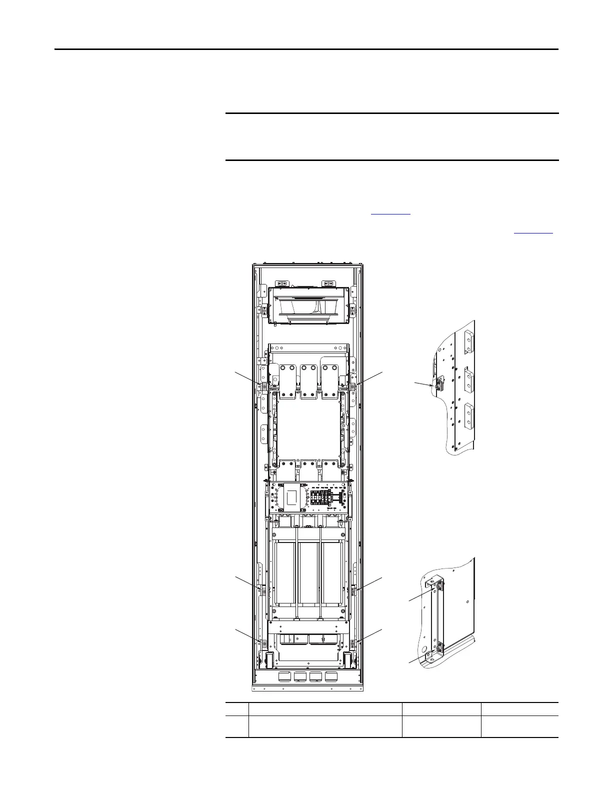
2. Disconnect the six captive bolts connecting the cabinet options assembly
to the cabinet frame (No. ➊ Figure 81
).
3. Disconnect the wiring harnesses and bus connections shown in Figure 82
.
Figure 81 - Cabinet Options-To-Cabinet Connections
Before removing the cabinet options assembly, be sure the cabinet is in its
intended installed position. Height adjustments to the roll-out cart can not be
made while carrying the assembly.
No. Description Torque Recommended Tool
➊ Cabinet options assembly-to-cabinet anchor bolts (6
places).
11.3 N•m (100 lb•in) 5 mm hex key (Allen)

 Loading...


