Rockwell Automation Publication 750-IN001O-EN-P - October 2014 267
I/O Wiring Chapter 5
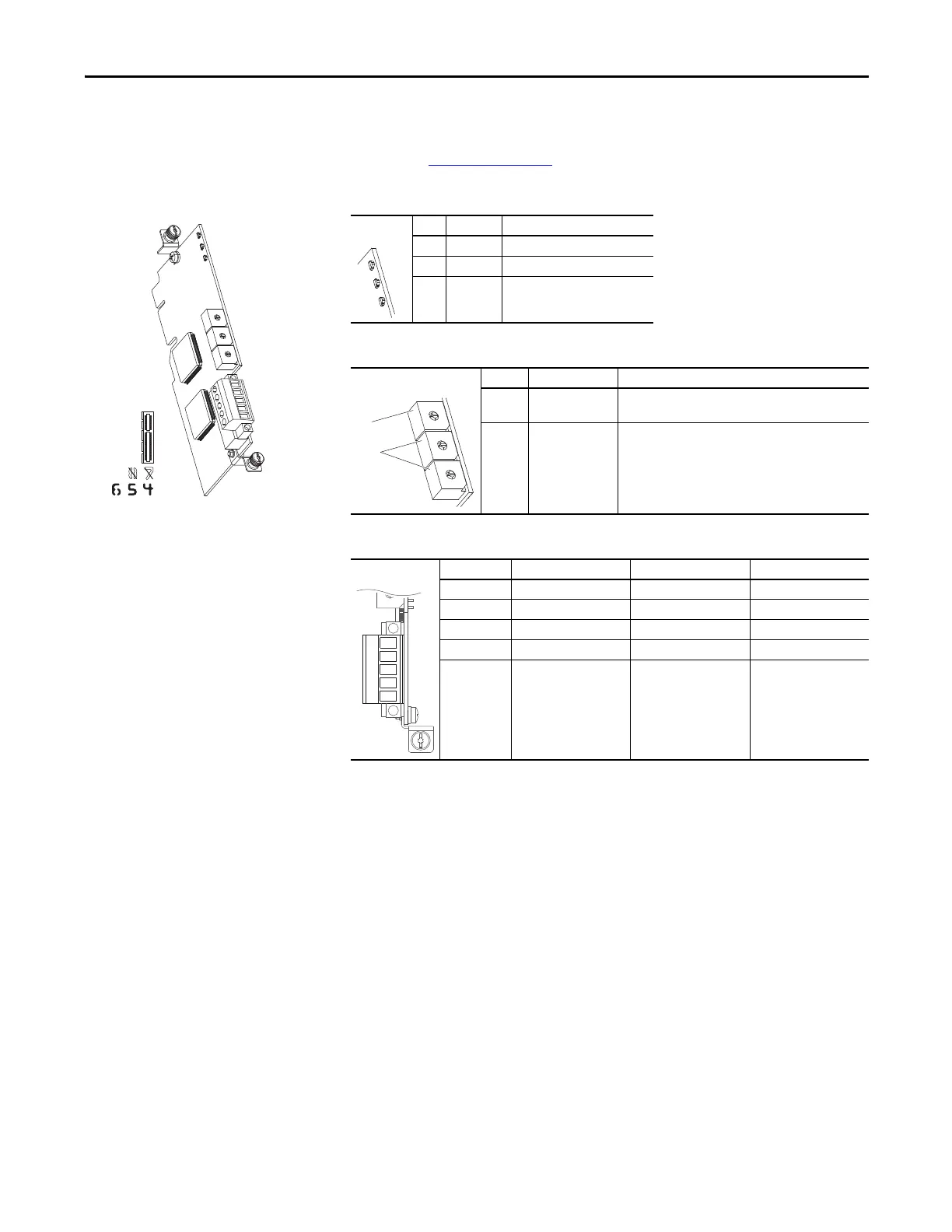
DeviceNet Option Module
For complete information on the DeviceNet Option Module, refer to the
PowerFlex 750-Series Drive DeviceNet Option Module User Manual,
publication 750COM-UM002
.
Table 67 - DeviceNet Option Module LED Indication
Table 68 - DeviceNet Option Module Rotary Switches
Table 69 - TB1 Terminal Designations
LED Name Description
➊ PORT DPI Connection Status
➋ MOD Option Module Status
➌ NET A DeviceNet Status
Switch Name Description
➊ Data Rate Switch Sets the DeviceNet data rate at which the option module
communicates.
➋ Node Address
Switches
Sets the node address of the option module.
Terminal Color Signal Function
5 Red V+ Power Supply
4 White CAN_H Signal High
3 Bare SHIELD Shield
2 Blue CAN_L Signal Low
1 Black V- Common
➊
➋
5
4
3
2
1

 Loading...


