Rockwell Automation Publication 750-IN001O-EN-P - October 2014 279
I/O Wiring Chapter 5
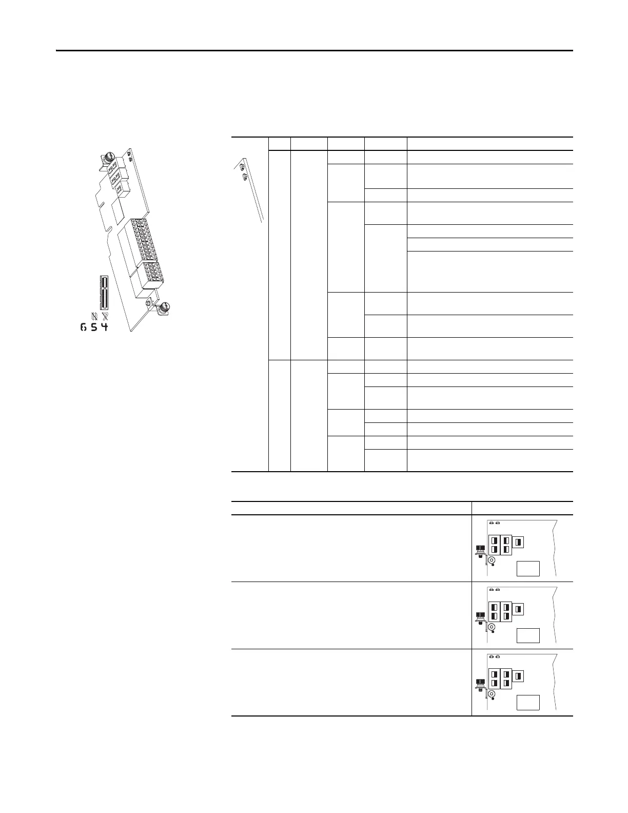
Universal Feedback Option
Module - 755 Drives Only
Table 91 - Universal Feedback Option Module LED Indication
Table 92 - Universal Feedback Option Module DIP Switch Settings - Safety Application
LED Name Color State Description
➊ Board Unlit Off Not powered.
Green Flashing Initializing, not active.
Communication lost, attempting to reconnect.
Steady Operational, no faults are present.
Red Flashing Module error.
• Check P1 [Module Sts]
Steady Normal operation.
Module is booting.
Fatal module error.
• Cycle power
• Flash update module firmware
• Replace module
Yellow Flashing A type 2 alarm condition exists.
• Check P1 [Module Sts]
Steady A type 1 alarm condition exists.
• Check P1 [Module Sts]
Yellow /
Green
Flashing
Alternately
Module is flash updating.
➋ DPI Unlit Off Not powered. Not communicating.
Green Flashing Module is attempting to communicate with the DPI host.
Steady • Properly connected and communicating.
• Module is flash updating.
Red Flashing Module is not communicating with the DPI host.
Steady DPI communication failure such as invalid port.
Yellow Flashing Normal operation.
Steady Peripheral is connected to a SCANport product and does
not support a SCANport compatibility mode.
Safety Channel Selection DIP Switch Settings
(1)
(1) DIP switches only function when safety channels are used.
Primary Safety Channel
To connect feedback signals to the Primary Safety Channel, set:
S1 sliders to ON
S2 sliders to OFF
S3 slider to ON
Secondary Safety Channel
To connect feedback signals to the Secondary Safety Channel, set:
S1 sliders to OFF
S2 sliders to ON
S3 slider to ON
Primary and Secondary Safety Channels
To connect feedback signals to both the Primary and Secondary Safety Channels, set:
S1 sliders to ON
S2 sliders to ON
S3 slider to ON
➊
➋

 Loading...


