EasyManuals Logo
Home>Allen-Bradley>Controller>PowerFlex 20-750-S1

Allen-Bradley PowerFlex 20-750-S1 User Manual

Allen-Bradley PowerFlex 20-750-S1
302 pages
To Next Page IconTo Next Page
To Previous Page IconTo Previous Page
Page #123 background imageLoading...
Page #123 background image
Rockwell Automation Publication 750-IN001O-EN-P - October 2014 123
Lift and Mount the Drive Chapter 3
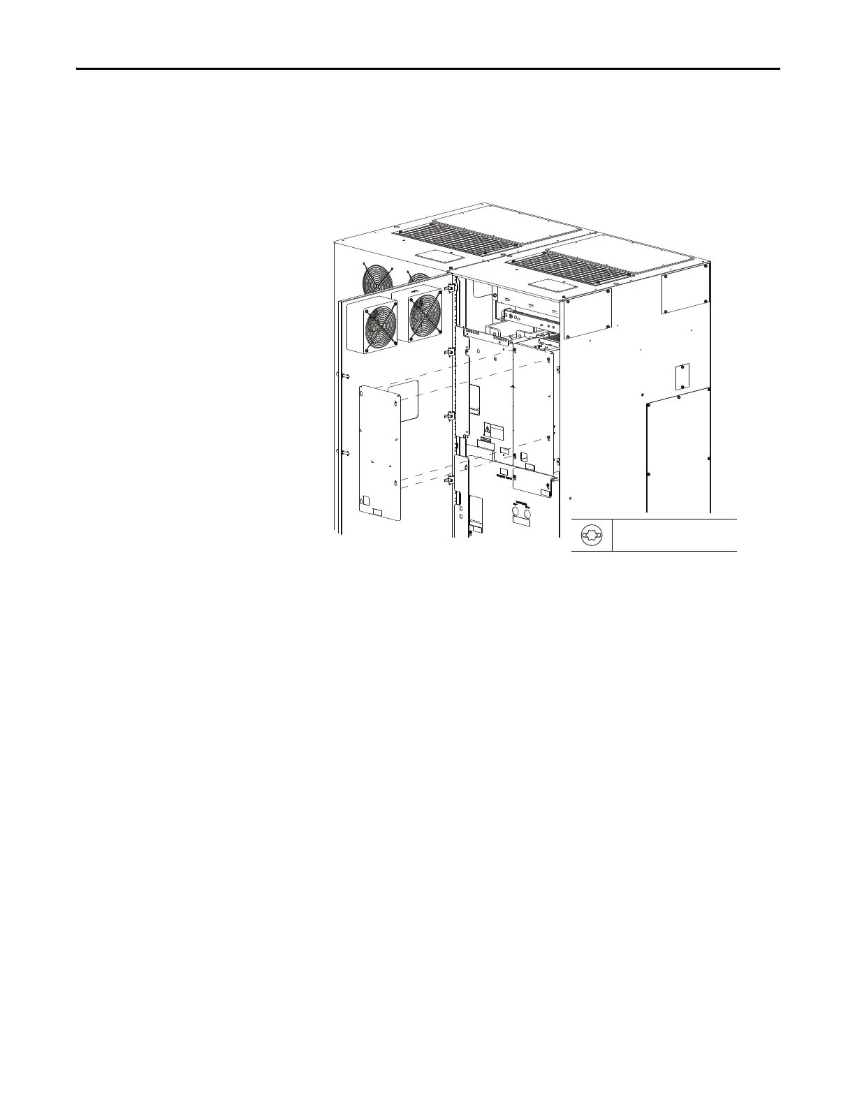
Disconnect Wire Connections
- No Drive Control Pod
This procedure applies to Frame 8 drives with a remotely mounted drive control
pod (up to 23 m or 75 ft away) and to the right hand cabinets of Frame 9 and
larger drives.
1. Remove the right front cover.
2. Disconnect the 24V wire harness from TB1.
3. Disconnect the fiber-optic cable from INV on the power layer interface
board.
T20 or F 6.4 mm (0.25 in.)
1.8 N•m (16.0 lb•in)
Floor Mount Frame 9 Shown

Table of Contents

Questions and Answers:

Question and Answer IconNeed help?

Do you have a question about the Allen-Bradley PowerFlex 20-750-S1 and is the answer not in the manual?

Allen-Bradley PowerFlex 20-750-S1 Specifications

General IconGeneral
BrandAllen-Bradley
ModelPowerFlex 20-750-S1
CategoryController
LanguageEnglish

Related product manuals