226 Rockwell Automation Publication 750-IN001O-EN-P - October 2014
Chapter 5 I/O Wiring
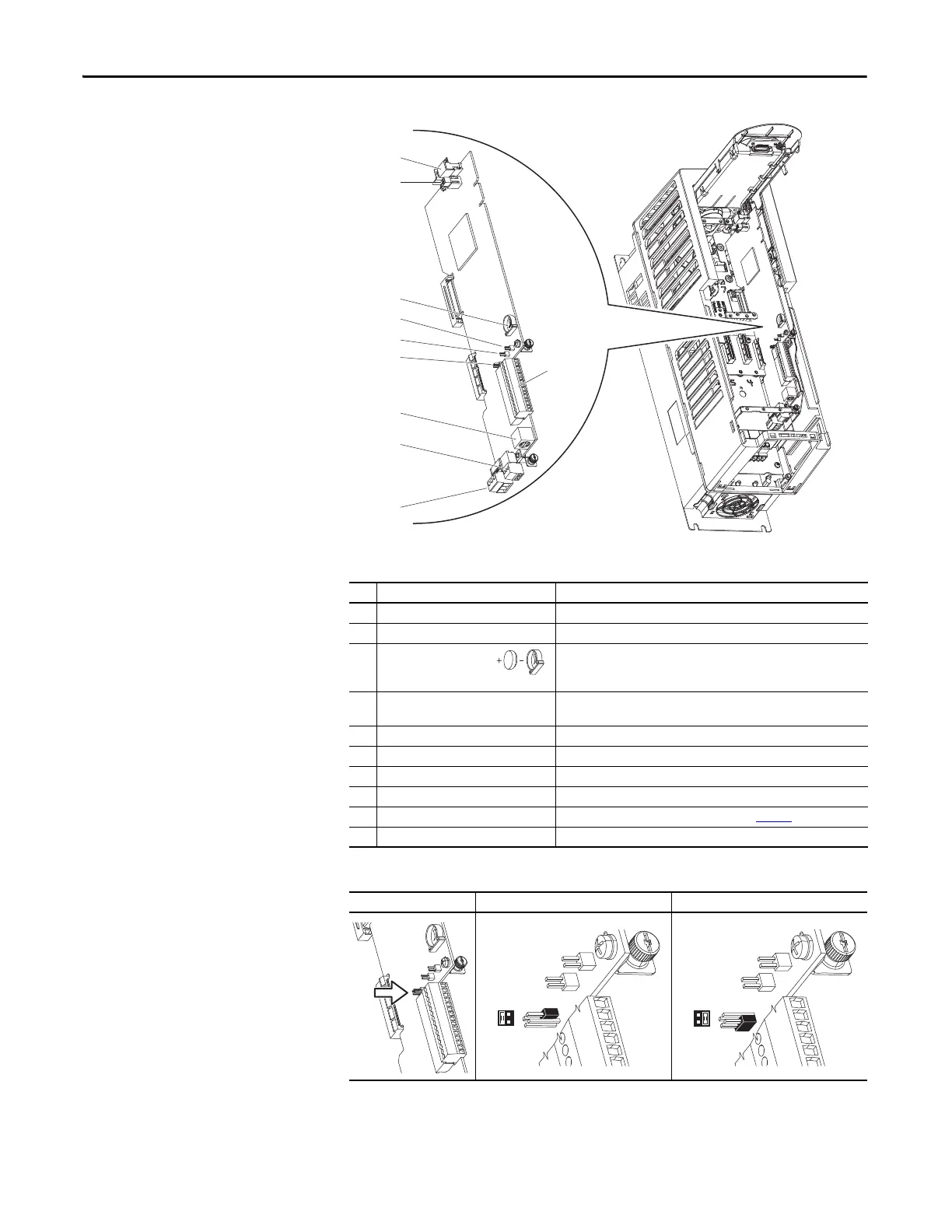
PowerFlex 753 Main Control
Board
Table 36 - 753 Main Control Board Details
Table 37 - J4 Input Mode Jumper
No. Name Description
➊ HIM Connector DPI Port 1 (HIM Cradle) connection.
➋ Fan Connector Power supply for internal cooling fan (Frames 2 & 3).
➌ Battery Receptacle User installed CR1220 lithium coin cell battery provides power to the
Real Time Clock (Optional, not supplied). Preserves the Real Time Clock
setting in the event power to the drive is lost or cycled.
➍ ENABLE Jumper Hardware enable jumper. TB3 becomes an Enable when this jumper is
removed.
➎ SAFETY Jumper Safety enable jumper. Removed when safety option is installed.
➏ Jumper J4 Input Mode Analog input mode jumper. Selects voltage mode or current mode.
➐ TB1 I/O terminal block.
➑ DPI Port 2 Cable connection for handheld and remote HIM options.
➒ TB3 Digital input terminal block. See Important at Table 40
.
➓ TB2 Relay terminal block.
Jumper Position Voltage Mode Current Mode
➊
➋
➌
➍
➑
➏
➎
➒
➓
➐
SK-R1-MCB1-PF753
J4
3 1
4 2
J4
3 1
4 2

 Loading...


