Rockwell Automation Publication 750-IN001O-EN-P - October 2014 149
Power Wiring Chapter 4
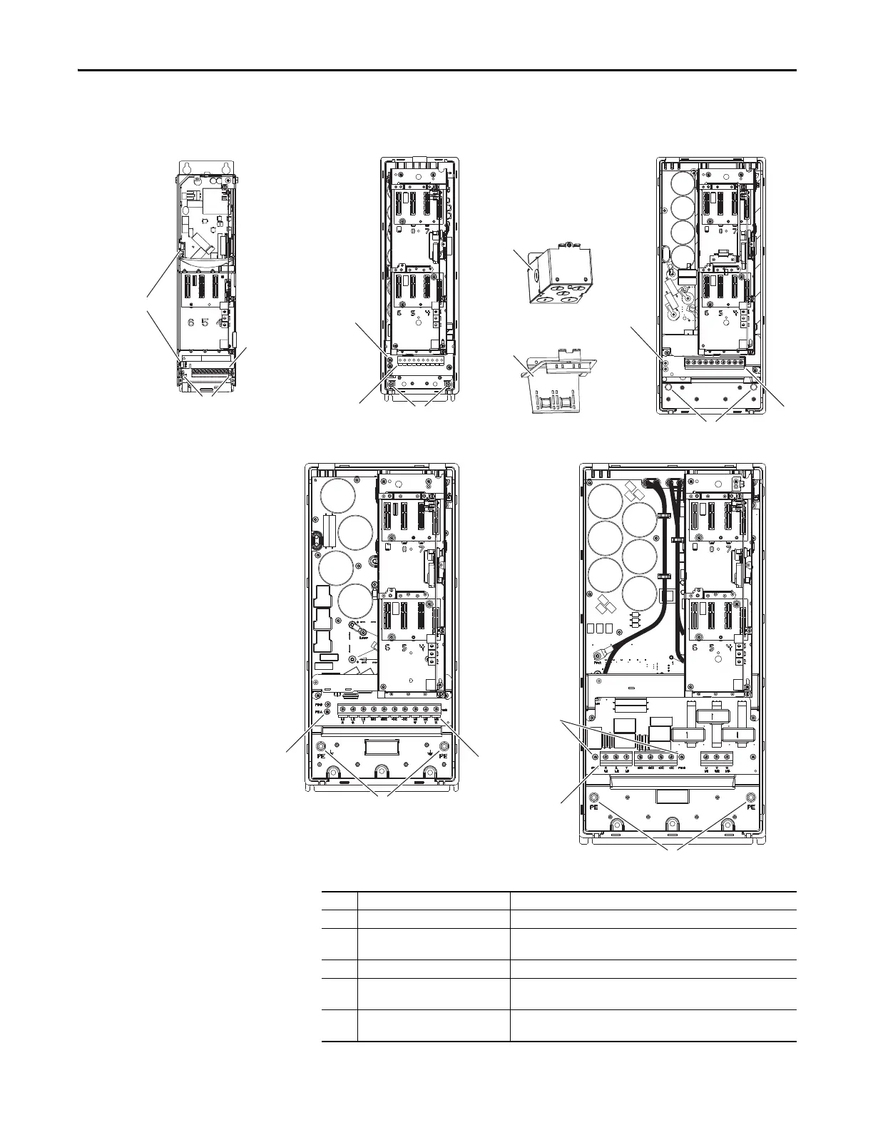
Three-Phase Terminal
Locations
Figure 88 - Wall Mount Frames 1…5 Power Terminal Block and Termination Point Locations
Wall Mount Frame 2
Wall Mount Frame 3
Wall Mount Frame 4
Wall Mount Frame 5
Wall Mount Frame 1
No. Name Description
➊ Power Terminal Block R/L1, S/L2, T/L3, BR1, BR2, +DC, -DC, U/T1, V/T2, W/T3
➋ PE Grounding Studs Terminating point to chassis ground for incoming AC line and motor
shields.
➌ PE-A and PE-B MOV and CMC Jumpers
➍ Optional NEMA/UL Type 1 Conduit
Box
Terminating point to chassis ground for incoming AC line, motor
shields, and control wire shields.
➎ Optional EMC Plate Terminating point to chassis ground for incoming AC line, motor
shields, and control wire shields.

 Loading...


