Rockwell Automation Publication 750-IN001O-EN-P - October 2014 295
I/O Wiring Chapter 5
Control Wiring - Current
Frame 8 Drives with Cabinet
Options
Frame 8 drives are shipped from the factory with control power set to 120V AC.
To change control voltage to 230V AC, move the jumper as shown.
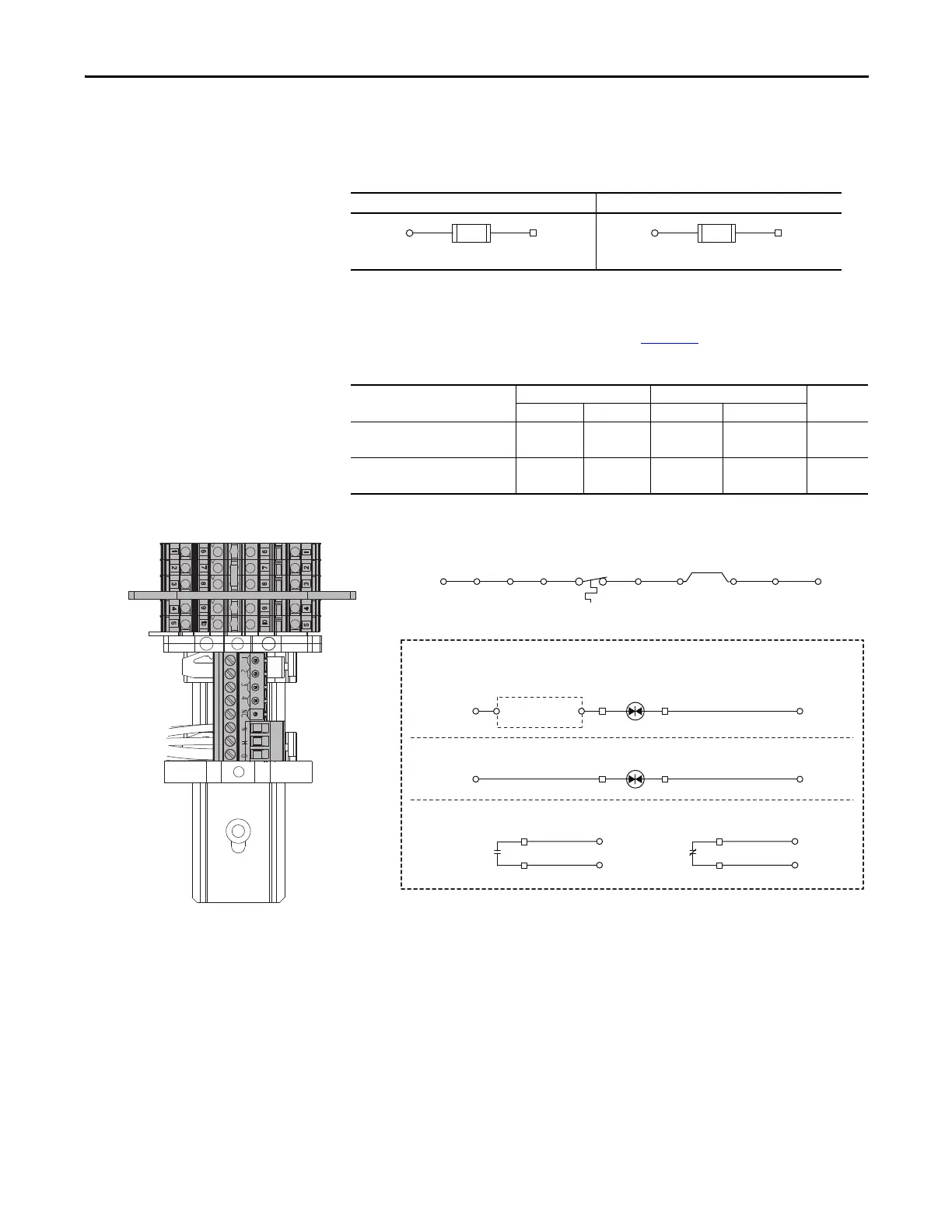
Table 99 - Control Power for Customer Use Voltage Selection - Floor Mount Frame 8 Drives
Control terminal block TB4 is mounted on the inside right panel of the cabinet
options bay in current production drives. TB1 referenced in the illustrations
below resides on the main control board. See page 229
.
Table 100 - TB4 Terminal Block Specifications
Figure 159 - Control Terminal Blocks TB3 and TB4 - Floor Mount Frame 8 Drives
120V AC, 60Hz, 4.2A (Factory Setting) 230V AC, 50Hz, 2.2A
Name Wire Size Range Torque Strip
Length
Maximum Minimum Maximum Recommended
Control Terminal Block TB3 4.0 mm
2
(12 AWG)
0.2 mm
2
(24 AWG)
0.5 N•m
(4.5 lb•in)
0.4 N•m
(3.5 lb•in)
7 mm
(0.28 in.)
Control Terminal Block TB4 4.0 mm
2
(12 AWG)
0.5 mm
2
(20 AWG)
0.5 N•m
(4.5 lb•in)
0.4 N•m
(3.5 lb•in)
8 mm
(0.32 in.)
TB3(H)TB4(7)
FU12
600V AC, 3A, Class CC
TB3(H)TB4(6)
FU12
600V AC, 6A, Class CC
Input/Output Contactor with or without X1 Option
TS1
Thermostat
TB6(1)TB4(4)TB4(10)TB6(4)TB6(3)TB4(5)TB6(2)
TB1(+24V)
TB1(Di 0dc)
13
14
TB3(1)
TB3(4)
M2/M4
21
22
TB3(2)
TB3(3)
M2/M4
Optional Devices
M2/M4
TB4(3)
A1 A2
TB4(2)
Contactor without X1 Option
M2/M4
TB4(3)
A1 A2
TB4(2)
Contactor with X1 Option
Customer Supplied
Control Circuit
TB3
TB4

 Loading...


