240 Rockwell Automation Publication 750-IN001O-EN-P - October 2014
Chapter 5 I/O Wiring
120/240V AC Power Supply
Connections - Common DC
Input Drives
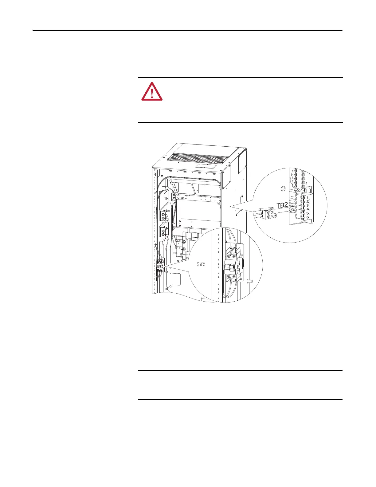
The drive-supplied 120/240V AC is wired through a circuit breaker mounted in
the Common DC Input drive cabinet. The circuit breaker is connected to TB2-3
and TB2-4 on the Common DC Input drive control panel.
Figure 131 - 120V Connection Terminals - Floor Mount Frames 8…10
This 13 A circuit breaker provides branch-circuit short-circuit and overcurrent
protection for the wiring on the primary side of the control transformer, and
protection of the transformer primary. Transformer secondary protection (240V
output) is provided through a 5 A, 600V, Class CC, time delay fuse.
ATTENTION: To avoid an electric shock hazard when servicing the drive, a
means for Lockout/Tagout of an external 120/240V power source must be
provided. Or the circuit breaker SW5 must be locked and tagged. Locking and
tagging the common bus precharge disconnect switch SW2 alone does not
provide sufficient protection when servicing the drive.
The transformer primary wiring is internally wired through the DC input drive
disconnect switch SW2 ahead of the control transformer primary terminal
connections.

 Loading...


