36 Rockwell Automation Publication 750-IN001O-EN-P - October 2014
Chapter 3 Lift and Mount the Drive
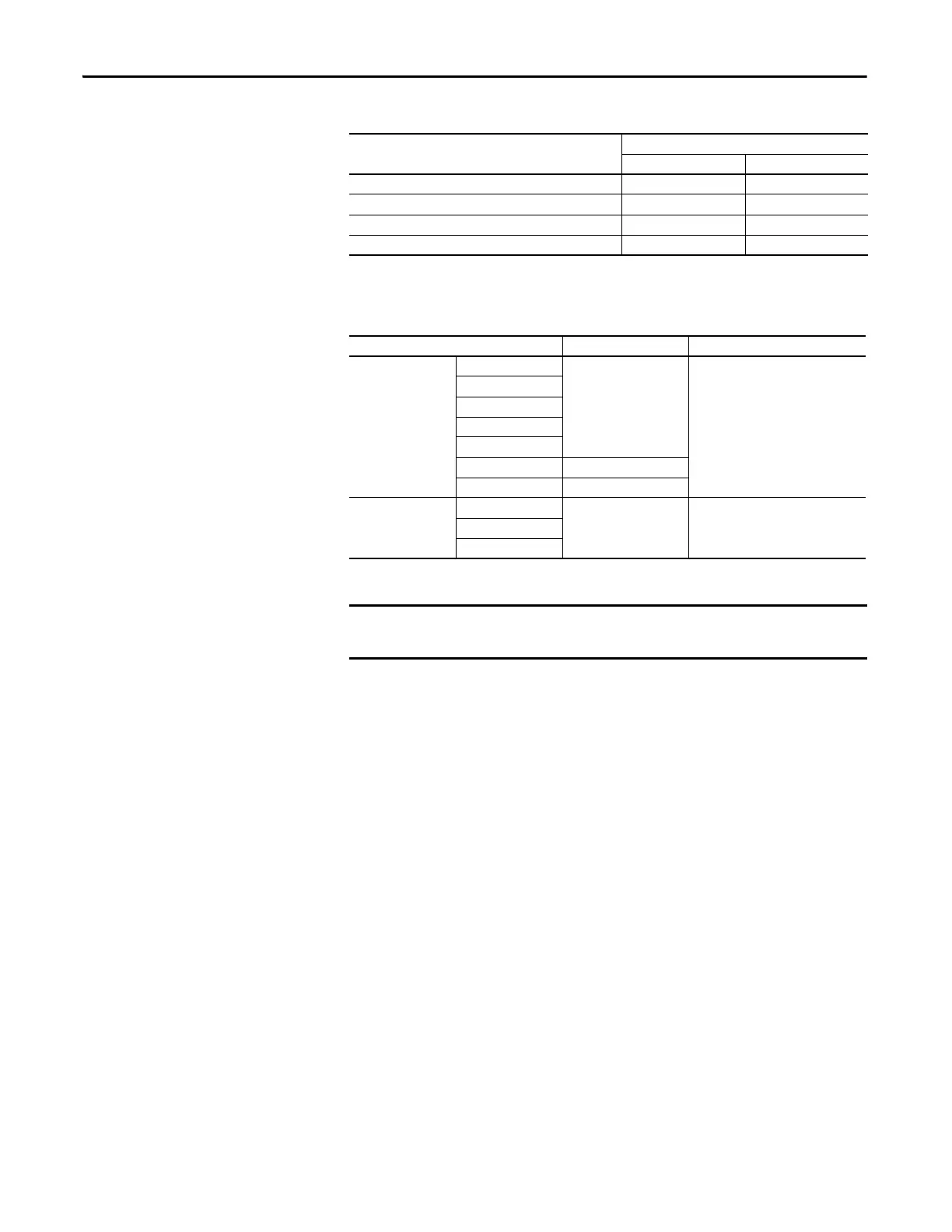
Table 4 - Maximum Component Weights - Floor Mount Frames 8…10
Recommended Mounting
Hardware
Component Weight kg (lb)
AC Input Common DC Input
Converter/DC Input w/Precharge 64 (140) 64 (140)
Inverter 222 (490) 165 (363)
Drive Assembly (Open, IP00) 286 (630) 229 (504)
Cabinet Options Assembly with Circuit Breaker and Reactor 296 (653) –
Frame Size Fastener Size Notes
Wall Mount
1
M6 (#10 or #12)
2
3
4
5
6 M6 (#12)
7M8 (5/16 in.)
Floor Mount
8
M12 (1/2 in.) Property Class 8.8 (Minimum)9
10
Mounting hardware is provided with enclosure type F (Flange mount) drives.
The hardware supplied must be used to meet the enclosure rating.

 Loading...


