Rockwell Automation Publication 750-IN001O-EN-P - October 2014 233
I/O Wiring Chapter 5
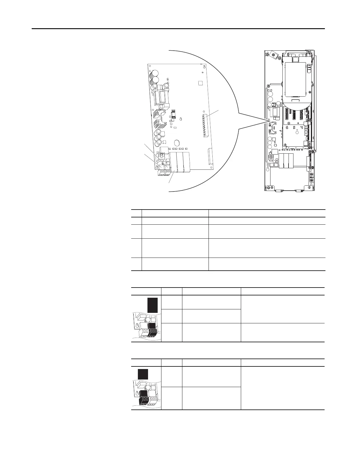
PowerFlex 755 Fiber Optic
Interface Board
Figure 126 - Floor Mount Frames 8…10
Table 45 - Fiber Interface Board Details
Table 46 - P13 Terminal Designations
Table 47 - P14 Terminal Designations
No. Name Description
➊ Main Control Board Connector 98 pin main control board interface connection.
➋ P13 Connections for user-supplied 24 volt power.
Powers control circuits when main power is removed.
➌ P14 Connections for internal drive-supplied 24 volt power. Connection is
factory wired and must not be modified by the user.
Powers control circuits when main power is connected.
➍ Inverter Connections Fiber optic ports: P1 = INV1, P2 = INV2, P3 = INV3, P4 = INV4, P5 =
INV5
Power Block Terminal Name Description
AP+ +24 Volt Auxiliary Power Connections for customer supplied power supply:
24V DC ±10%, 5 A, PELV (Protective Extra Low
Voltage) or SELV (Safety Extra Low Voltage)
AP– Auxiliary Power Common
Sh Shield Terminating point for wire shields.
Power Block Terminal Name Description
1 +24 Volt Power Connections for drive supplied power.
2Power Common
➍
➊
P1 P2 P3
➌
➋
SK-R1-FIB1-F8

 Loading...


