Rockwell Automation Publication 750-IN001O-EN-P - October 2014 147
Power Wiring Chapter 4
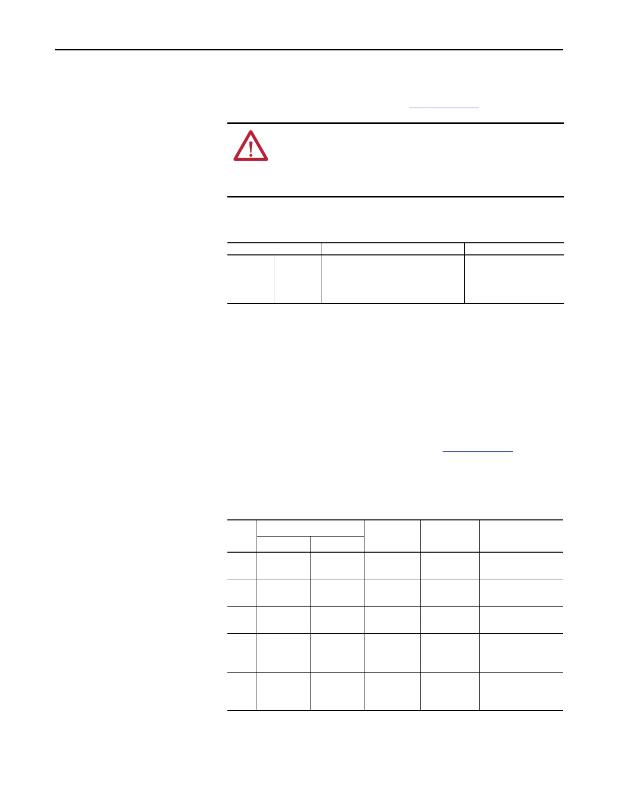
Power Cable Types
Acceptable for 200…600
Volt Installations
For detailed information on a variety of cable types that are acceptable for drive
installations, refer to Wiring and Grounding Guidelines for Pulse Width
Modulated (PWM) AC Drive, publication DRIVES-IN001
.
Wire Recommendations
Motor Considerations
Due to the operational characteristics of AC variable frequency drives, motors
with inverter grade insulation systems designed to meet or exceed NEMA MG1
Part 31.40.4.2 standards for resistance to spikes of 1600 volts are recommended.
Guidelines must be followed when using non-inverter grade motors to avoid
premature motor failures. Refer to Wiring and Grounding Guidelines for Pulse
Width Modulated (PWM) AC Drives, publication DRIVES-IN001
for
recommendations.
Terminal Block Specifications
Table 7 - Wall Mount Frames 1…5 Power Terminal Block
ATTENTION: National Codes and standards (NEC, BSI and so forth) and local
codes outline provisions for safely installing electrical equipment. Installation
must comply with specifications regarding wire types, conductor sizes, branch
circuit protection and disconnect devices. Failure to do so may result in personal
injury and/or equipment damage.
Type Description Min. Insulation Rating
Power
(1)(2)
(1) Control and signal wires should be separated from power wires by at least 0.3 meters (1 foot).
(2) The use of shielded wire for AC input power may not be necessary but is always recommended.
Standard • Four tinned copper conductors with XLPE
insulation.
• Copper braid/aluminum foil combination
shield and tinned copper drain wire.
• PVC jacket.
600V,
75 °C (167 °F)
Frame Wire Size Range
(1)
(2)
(1) Maximum/minimum wire sizes that the terminal block will accept - these are not recommendations.
(2) Terminal blocks are designed to accept a single wire.
Strip Length Recommended
Torque
Recommended Tool(s)
Maximum Minimum
14.0 mm
2
(10 AWG)
0.2 mm
2
(24 AWG)
8.0 mm
(0.31 in.)
0.57 N•m
(5 lb•in)
#2 Pozidrive®, M3 x 7
24.0 mm
2
(10 AWG)
0.2 mm
2
(24 AWG)
8.0 mm
(0.31 in.)
0.57 N•m
(5 lb•in)
#2 Pozidrive®, M3 x 7
3 16.0 mm
2
(6 AWG)
0.5 mm
2
(20 AWG)
10.0 mm
(0.39 in.)
1.2 N•m
(10.6 lb•in)
#2 Flat Screwdriver
4 25.0 mm
2
(3 AWG)
2.5 mm
2
(14 AWG)
10.0 mm
(0.39 in.)
2.7 N•m
(24 lb•in)
#2 Pozidrive®
492-C Phillips®
0.25 in. Flat Screwdriver
5 35.0 mm
2
(1 AWG)
10.0 mm
2
(8 AWG)
12.0 mm
(0.5 in.)
4.0 N•m
(35 lb•in)
#2 Pozidrive®
492-C Phillips®
0.25 in. Flat Screwdriver

 Loading...


