Rockwell Automation Publication 750-IN001O-EN-P - October 2014 153
Power Wiring Chapter 4
Wall Mount Frames 5…7
Common DC Input Terminal
Locations
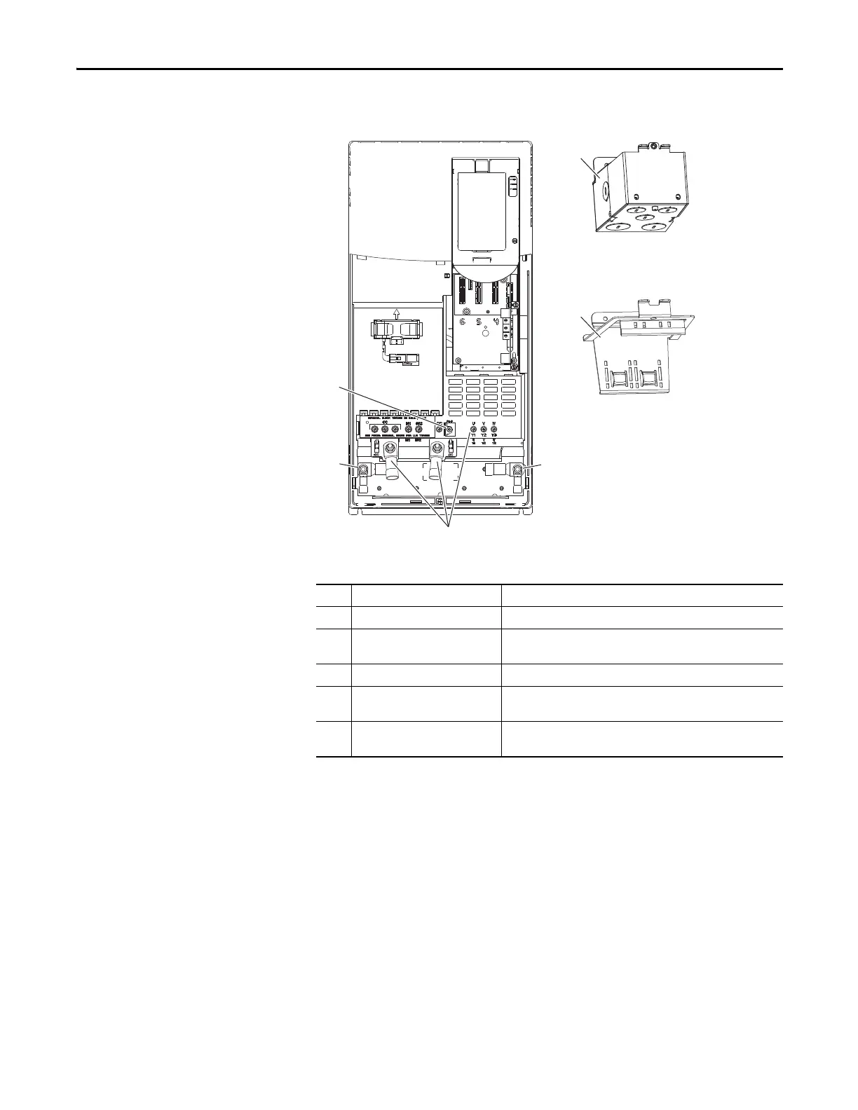
Figure 90 - Wall Mount Frame 5 Common DC Input Power Terminal and Termination Point
Locations
No. Name Description
➊ Power Terminal Connections +DC, -DC, U/T1, V/T2, W/T3
➋ PE Grounding Studs Terminating point to chassis ground for incoming DC line and motor
shields.
➌ PE-B CMC Jumper Screw
➍ Optional NEMA/UL Type 1 Conduit
Box
Terminating point to chassis ground for incoming AC line, motor
shields, and control wire shields.
➎ Optional EMC Plate Terminating point to chassis ground for incoming AC line, motor
shields, and control wire shields.
➊
➌
➋
➋
➍
➎

 Loading...


