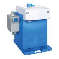
6.4.4 [Stroke] Stroke signal output
The switching output is closed once with each stroke of the pump.
Relay output = potential-free transistor output, load 24 V
, DC, 300 mA
4 = - (minus)
5 = + (plus)
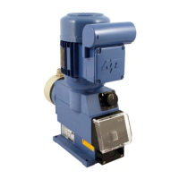
6.4.5 [BUS] Internal BUS connection
6 = GND
7 = CAN L
8 = CAN H
9 = 24 V
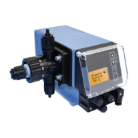
6.4.6
[Flow] Metering monitoring (e.g. with oval gear meter OGM
PLUS
)
10 = Bus (oval gear meter)
Colour: White
1
1 = GND
Colour: Blue
12 = Flow monitoring
Colour: Black
13 = 5 volts
Colour: Brown
6.4.7 [Diaphragm] Diaphragm breakage monitoring
For the software-side configuration, see
Ä
Chapter 7.10.15 ‘Diaphragm
breakage’ on page 124
Mounting and installation
59 417102276 Rev. 5-02.2020
 Loading...