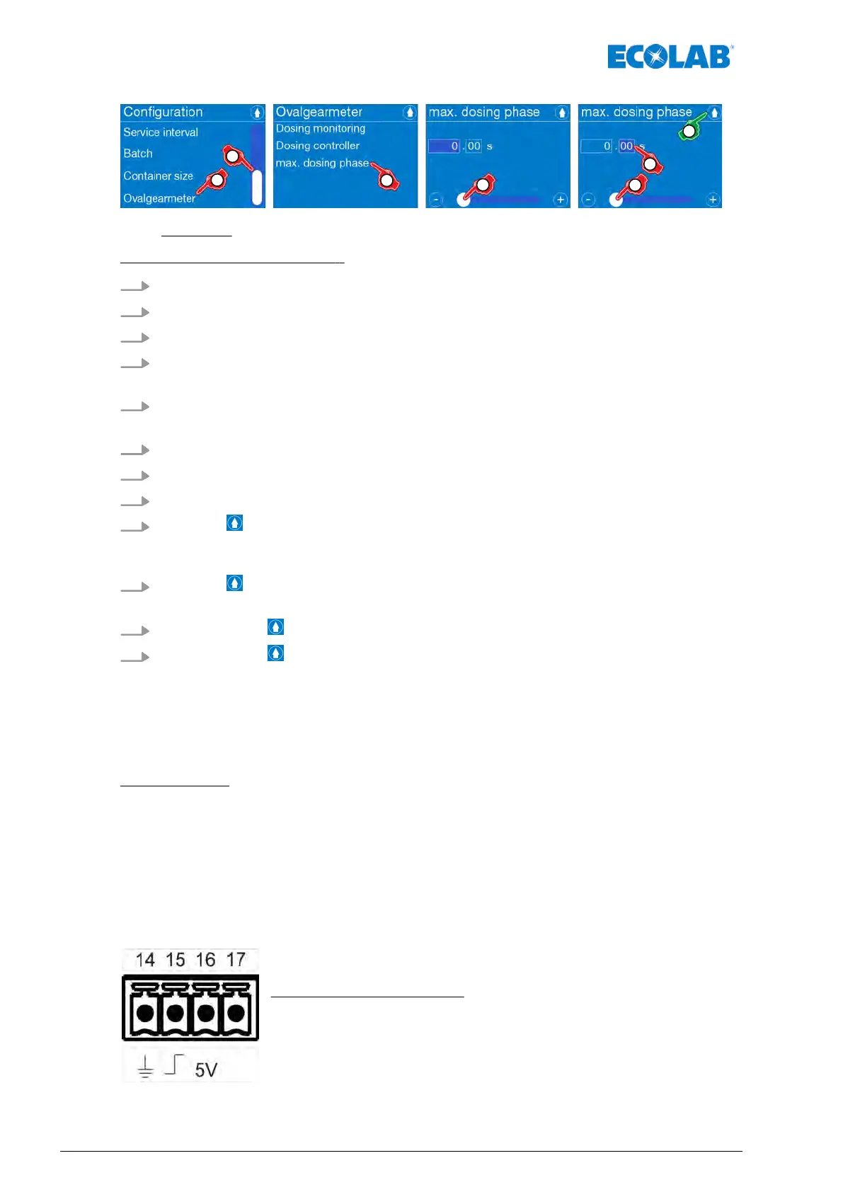
Fig. 72: Configuration: Max. metering phase
[Select Max. metering phase] :
1.
[Call up the Main menu] :
Ä
Chapter 7.7 ‘Main menu’ on page 73
2.
[Select Configuration] :
Ä
Chapter 7.10 ‘Overview - Configuration’ on page 92
3. Use the scrollbar to scroll to the [Oval gear meter] menu item.
4. [Select Oval gear meter] .
ð
Screen switches to the [selection Oval gear meter].
5. [Select Max. metering phase] .
ð
Screen change for the setting: [Max. metering phase]
6. Enter the seconds before the decimal point with the scrollbar
.
7. Select the seconds after the decimal point.
8. Enter the seconds with the scrollbar
.
9.
Press the button.
ð
The setting is saved, and the screen switches back to the menu
[Oval gear meter]
.
10.
Press the button.
ð
The setting is saved, and the screen switches back to the configuration overview
.
11.
By pressing the button, you can return to the [main menu].
12.
By pressing the button, you can return to the [operating display].
7.10.15 Diaphragm breakage
Under ‘diaphragm breakage
’ the monitoring of the pump diaphragm is switched on or off.
Requirements:
n This function can only be used when a pump head of 30 l/h, 50 l/h or 120 l/h size is
installed on the pump with the respective diaphragm protection sensor
.
n Select the corresponding sensor for diaphragm breakage
Ä
Chapter 12.2.4 ‘Pump
head 30 l/h and 50 l/h’ on page 173, pos. 9 or
Ä
Chapter 12.2.5 ‘Pump head 120 l/h’
on page 174, pos. 11 and install.
Electric connection - Sensor for diaphragm breakage
The electric connection is done on the main board
Ä
Chapter 6.4.7 ‘[Diaphragm] Diaphragm breakage monitoring ’ on page 59
The connections are as follows:
14 = GND
15 = Diaphragm
16 = 5 V
olt
17 = Anode
Control / Software
124417102276 Rev. 5-02.2020
 Loading...