FEASA LED ANALYSER
ICT VERSION
Capture Sequence Mode
Capture Sequence Sync Serial Commands
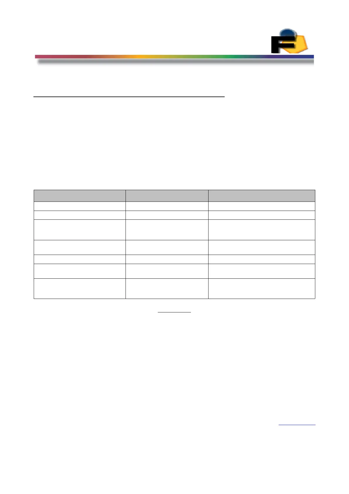
The following table lists the sequence capture commands that can be executed through the
Synchronous Serial Port.
These commands are in addition to the Synchronous Serial described above in the
Synchronous Serial Section
All data transmitted and received is in a binary format. The Most Significant Bit (MSB) is
transmitted/received first.
Command Data Transmitted Data Received
Clear Comms Buffer 0xFF (1 byte)
Initialize the LA 0xAA (1 byte) RyBy_bar goes high then low
Capture Sequence setup 0xC0+Capture Time (2 byte)+
Wait Time (2 byte) + No of
captures (2 bytes)
RyBy_bar goes high then low
Capture Sequence Intensity
Threshold
0xC1+ Intensity (3 bytes) RyBy_bar goes high then low
Execute Capture Sequence 0x45 RyBy_bar goes high then low
Read Intensity Capture Sequence 0x91+Fiber num (1 byte)+
Sequence Capture num (2bytes)
Intensity (3 bytes)
Read Pulse Times 0x92+Fiber num (1 byte) Time Off Beginning (2 bytes)
Time On (2 bytes)
Time Off End (2 bytes)
Figure 26.
Note:- The code 0xD5 indicates the command completed correctly. If the code 0xEE is
received then an error has occurred and the command should be re-transmitted.
Back to Index
137