FEASA LED ANALYSER
ICT VERSION
In-Circuit Test Mode
ICT Connector Pin-out
The ICT Port consists of a 20-way connector which includes all the signals necessary to
interface with the LED Analyser. These pins are shown in Figure 8.
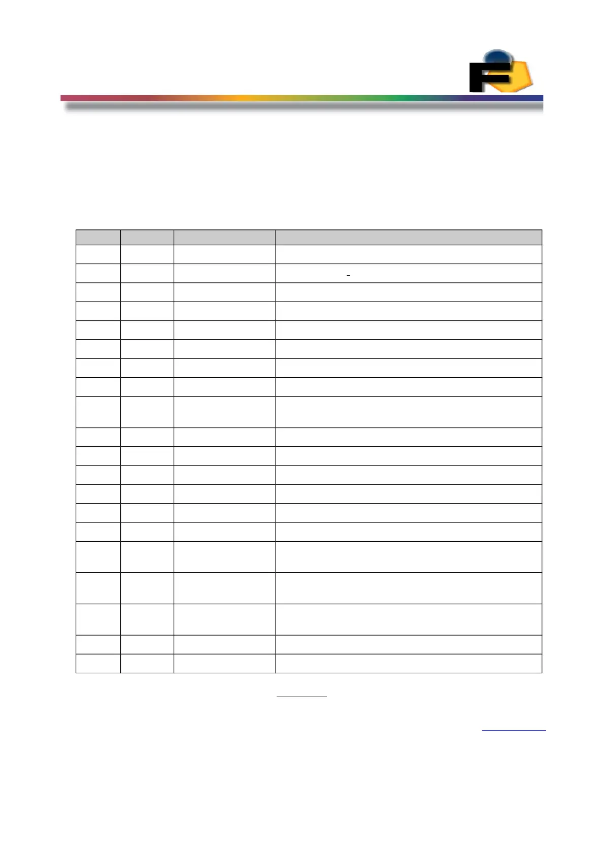
Pin Type Name Function
1 Output Ser_Out Synchronous Serial Output
2 Input Ser_In Synchronous Serial Input
3 Input SCK Synchronous Serial Clock
4 Ground GND Ground
5 Input Reset Reset input
6 Input /OE Output Enable – Active low
7 Input Trigger For External Capture
8 Input PWM_bar Select PWM mode - Active low.
9 Input Addr0/LA_Select LSB of Fiber Address (also used for Synchronous
Serial mode)
10 Input Addr1 Fiber Address
11 Input Addr2 Fiber Address
12 Input Addr3 Fiber Address
13 Input Addr4 MSB of Fiber Address
14 Input /WE Active Low.
15 Output Int_freq Frequency Out Square wave for Intensity
16 Output colour_freq Frequency Out Square wave for colour,
Wavelength, x Chromaticity
17 Output Sat_freq Frequency Out Square wave for Saturation, y
Chromaticity
18 Output RyBy_bar Ready Busy Output (Also Used for Synchronous
Serial mode)
19 Power VCC Power Supply 5V DC at 180mA
20 Ground GND Ground
Figure 8.
Back to Index
17
 Loading...