EasyManua.ls Logo

Feasa ICT Series User Manual

Default Icon
145 pages
To Next Page IconTo Next Page
To Previous Page IconTo Previous Page
Page #82 background imageLoading...
Page #82 background image
FEASA LED ANALYSER
ICT VERSION
Get Data Mode
get7SEG# - Get the value of a 7 Segment Display
Transmit Receive
get7seg# x
Where:
# represents the Number 1 or 2
x represents the value of the display 0 - 9
Description
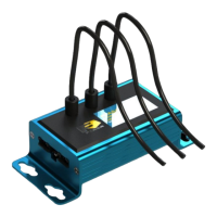
The LED Analyser can be used to test LED-based 7-Segment displays. To set up the LED
Analyser to interrogate a single 7-Segment display, fit fibers labelled 1 to 7 over segments a-g
on the 7-Segment display. See Figure 28 .
To set up the LED Analyser to interrogate an additional 7-Segment display, fit fibers labelled 11
to 17 over segments a-g on the additional display.
To interrogate the digit displayed on the first 7-Segment Display send the command get7seg1
to the LED Analyser. The LED Analyser will return the digit displayed. The LED Analyser will
return the character X when the displayed value is not recognized (0 to 9).
To interrogate the digit displayed on the second 7-Segment display send the command
get7seg2 to the LED Analyser. The LED Analyser will return the digit displayed. Again, the
LED Analyser will return the character X when the displayed value is not recognized (0 to 9).
Note:- it is not necessary to send any capture commands prior to using the get7seg1 or
get7seg2 commands.
Figure 28.
Example:
The PC transmits get7seg1 to the LED Analyser and the Analyser will return the value of the
display.
get7seg1
Back to Index
82
b
c
d
e
f
g
a

Table of Contents

Question and Answer IconNeed help?

Do you have a question about the Feasa ICT Series and is the answer not in the manual?

Feasa ICT Series Specifications

General IconGeneral
Operating Temperature0°C to 50°C
Storage Temperature-20°C to 70°C
ApplicationLED testing
Channels1
Communication InterfaceUSB
Power SourceUSB
Measurement ParametersDominant Wavelength, CCT, CRI
Accuracy±2% in flux

Summary

About this Manual

IMPORTANT INFORMATION for Programmers

Colour and Saturation

Intensity

White LED's

Setting Tolerance Limits for Colour and Intensity

In-Circuit Test Mode

Frequency Out Port Protocol

Details the protocol for data output via frequency signals.

ICT Connector Pin-out and Descriptions

Lists and describes the function of each pin on the ICT connector.

ICT Logic Levels & Cycle Times

Specifies electrical characteristics and timing for ICT interface.

In-Circuit Test Frequency Mode

Initialize the LED Analyser for Capture

Describes the procedure to initialize the analyser for data capture.

Set the Sensitivity Level of the Analyser (setfactor)

Capture LED Data (HSI or WSI or xyI) non PWM LED's

Capture LED Data (HSI or WSI or xyI) PWM LED's

Synchronous Serial Mode

Synchronous Serial Commands

Lists commands executable via the Synchronous Serial Port.

Capture for non-PWM LED's

Read Hue, Saturation and Intensity (HSI)

Read RGB and Intensity (RGBI)

Serial Port Control (RS232)

Capture Commands

AUTO CAPTURE - Store LED Data

Command to automatically capture and store LED data.

MANUAL CAPTURE# - Store LED Data for a specific range

Command to capture and store LED data for a specified range.

Get Data Commands

Under Range Condition

Describes conditions when LED light is insufficient for the selected range.

Over Range Condition

Describes conditions when LED light is excessive for the selected range.

getRGBI## - Get RGB and Intensity for a LED

getHSI## - Get Hue, Saturation and Intensity

General Commands

General Set Commands

Commands for adjusting various settings of the LED Analyser.

set/putFACTOR## - Set the Exposure Factor

set/putLOG - Change the Intensity Response of the Analyser to Logarithmic mode

General Get Commands

getSTATUS - Get a summary of the Led Analyser details

Retrieves a summary of the Analyser's configuration and status.

User Calibration Mode

setcalibration# - Select the user cal setting

Selects a specific user calibration set.

ResetUserCal - Reset the usercal setting to factory default

Resets the selected user calibration set to factory default values.

External Capture Mode

Set up the external capture

Configures the external capture function.

Sequence Capture Mode

Set/Put SequenceMode# - Set sequence mode for Fibers

Sets the sequence mode for using all or individual fibers.

Set/Put SequenceCapture##(#) - Set Sequence Capture Time

Sets the capture time in milliseconds for sequence capture.

Set/Put SequenceNumber###(#) - Set the Number of Captures

Sets the number of captures to store in sequence mode.

Set/Put SequenceThreshold##### - Set the Intensity Threshold

Sets an intensity threshold for binary conversion of readings.

CaptureSequence - Start the Captures

Starts the sequence capture function.

Step-by-Step approach to Testing a LED

PWM LED Mode

Effect of PWM on Intensity Testing

Explains the effect of PWM on intensity testing.

Testing a 7-Segment Display

Specifications

Warranty

Related product manuals