FEASA LED ANALYSER
ICT VERSION
In-Circuit Test Mode
Test LED Data (HSI or WSI or xyI)
This function is used to Read Back the Colour, Saturation, Dominant Wavelength, xy
Chromaticity & Intensity of a LED. Three frequencies representing these properties are output.
Each LED has a Fiber Address which must be input to the Analyser. A capture must be
executed prior to this function to ensure valid data is stored in the Analyser.
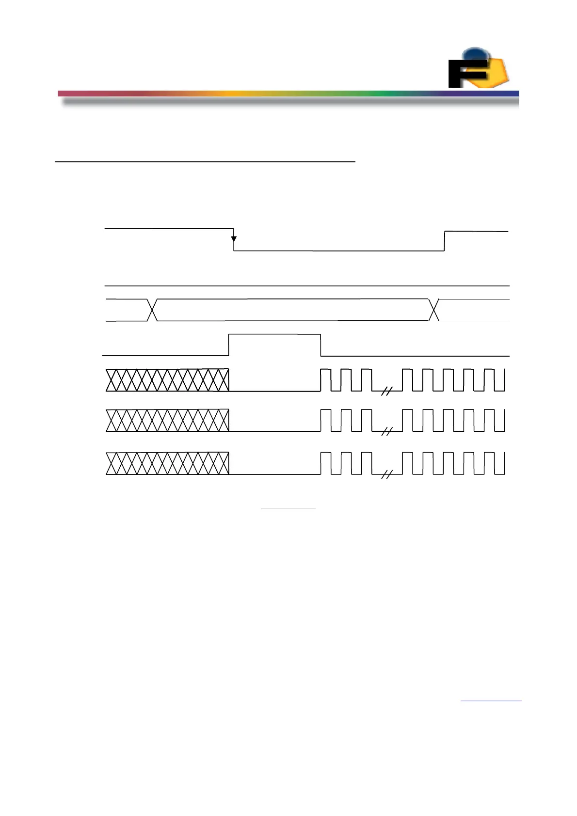
Figure 15.
The timing sequence is as follows:-
1/ Drive WE_bar High and drive OE_bar Low. RyBy_bar (pin18) will be driven low by the
Analyser.
2/ Select the Fiber Number you require (Figure 12) and Drive the address bus to this
code. (0001) for Fiber 1
3/ Drive WE_bar Low and the Analyser will drive RyBy_bar High. The Intensity (pin 15),
colour or Wavelength or x chromaticity (pin 16) and Saturation or y Chromaticity (pin
17) frequencies will be output on the ICT connector after the time T
calc .
RyBy_bar will
be driven low by the Analyser to indicate the outputs are valid. The time for T
calc
is
200mSec.
4/ Drive WE_bar High any time after RyBy_bar has gone Low.
Back to Index
28
WE_bar
OE_bar
Addr
Fiber
Addr
RY_BY
t
calc
Color
Freq
Intensity
Freq
Saturation
Freq
 Loading...