FEASA LED ANALYSER
ICT VERSION
In-Circuit Test Mode
Capture LED Data (HSI or WSI or xyI) non PWM LED's
This function will capture the Colour, Saturation and Intensity of all the LED's and store this
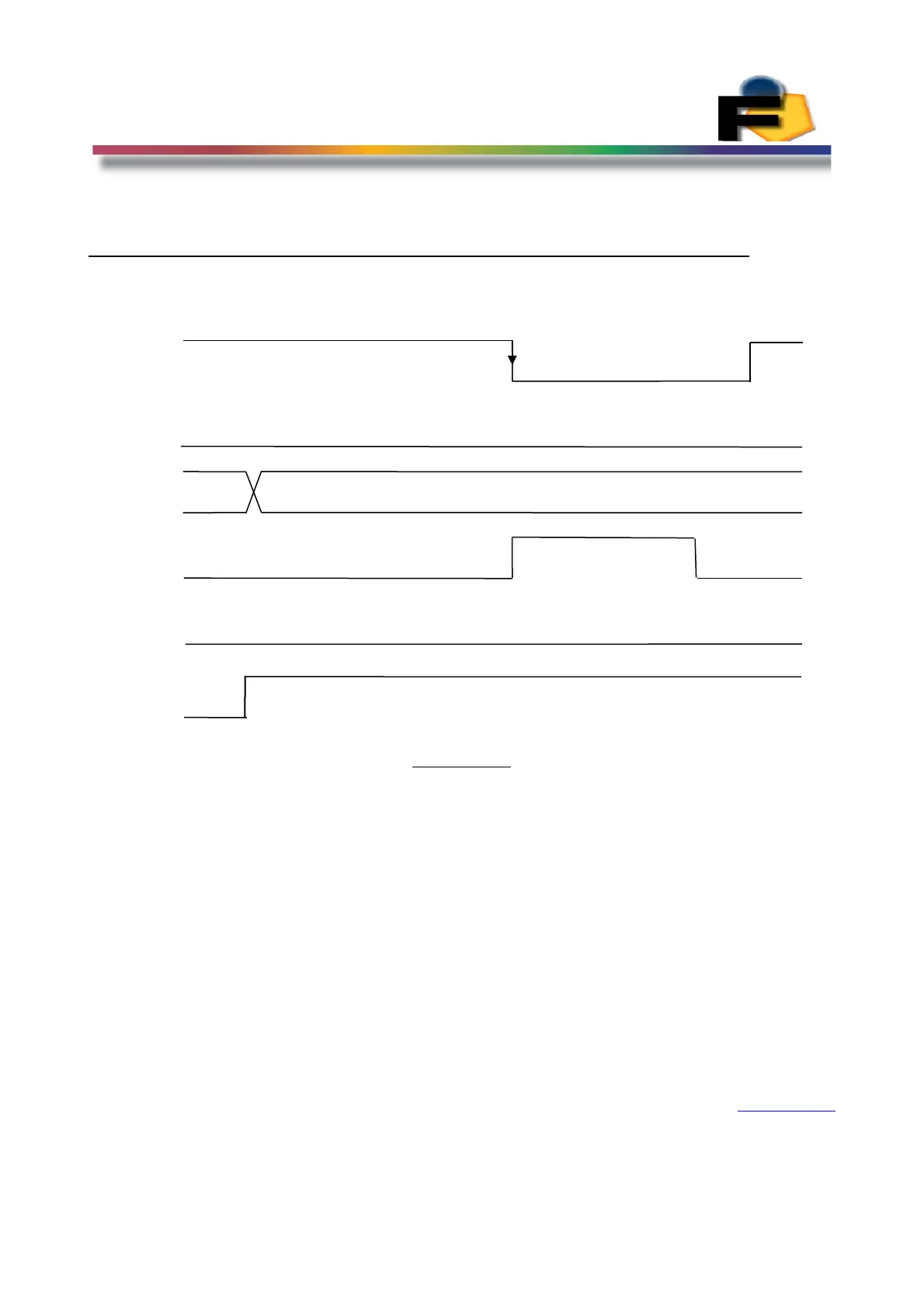
data in memory ready for output. The timing for this function is shown in Figure 14a.
Figure 14a.
The timing sequence is as follows:-
1/ Drive WE_bar High, PWM_bar High and OE_bar Low. RyBy_bar (pin18) will be
driven low by the Analyser. (**note PWM_bar has a pullup Res on the board so its optional to drive pin
8 high or not)
2/ Select the Capture Range you require (Figure 12) and Drive the address bus to this
code. (00000) for Auto Capture
3/ Drive WE_bar is Low and the Analyser will drive RyBy_bar high. All the frequencies
(from the previous capture) will be turned off at this time. After the time T
capture
RyBy_bar will be driven low by the Analyser to indicate it is ready for the next
function. The time for T
capture
will vary depending on the range selected. The test system
should loop on the RyBy_bar signal and wait for it to go low.
4/ Drive WE_bar High any time after RyBy_bar has gone Low.
Back to Index
26
WE_bar
OE_bar
Addr
Capture Address Code 0X00 or 0X15 - 0X1B
RY_BY
t
capture
Fout
PWM_bar
PWM_bar
 Loading...