CPU
VGA
USB 2.0
USB 2.0
USB 3.2
Gen 2
SSD1
M.2
M.2
SSD2
TPM
Slot 3
JP3
PWR1
FRONT
PWR2
P30
PC98
SERIAL
Intel
C256
USB 3.2
Gen 2
FAN3
SYS
FAN4
SYS
FAN5
SYS
FAN6
SYS
ODD
PWR
PANEL
TYPE C
FRONT
JP2 JP1
Clear RTC
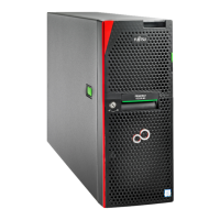
Figure 248: Slots for M.2 SSDs
1 M.2 SSD1 2 M.2 SSD2
15.6.2 Installing an M.2 SSD
Upgrade and Repair Unit
(URU)
Hardware: 5 minutes
Software: 15 minutes
Tools: tool-less
Preliminary steps
▶
If applicable, "Removing the front cover with lock" on page
45
.
▶
"Shutting down the server" on page 46.
▶
"Disconnecting the power cord" on page 47.
▶
"Getting access to the component" on page 49.
▶
Remove the riser module 2 and riser module 3, see "Removing a riser
module" on page 63.
System board and components
312 Upgrade and Maintenance Manual RX1330 M5
 Loading...