Appendix B. Using the Clamping Fixtures
100 PanaFlow™ LC User’s Manual
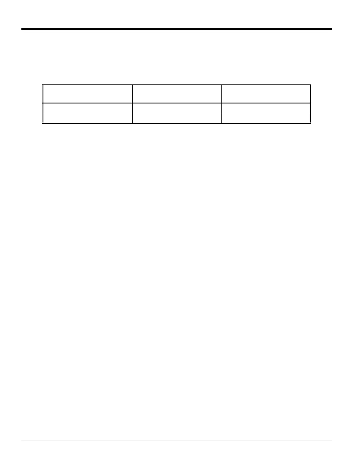
Before you begin the installation, make sure you note the application information in Table 2 below for your
clamping fixture. The UCF is available in 12" (300 mm) and 24" (600 mm) lengths. Both lengths can be used
for either odd traverse or even-traverse installations, but you must observe the pipe size ranges shown.
The transducer installation consists of mounting the UCF to the pipe and then mounting the transducers
into the fixture. Refer to the appropriate section for instructions on either the even-traverse or odd number
of-traverse methods.
B.1.1 Even Traverse Method
Note: The instructions in this section can also be used for a multiple-traverse method. However, you must use
an
EVEN number of traverses. The distance the signal travels from one side of the pipe wall to the
opposite side of the pipe wall is considered one traverse. For installations with more than two traverses,
contact BHGE for assistance.
There are two advantages to using the even number of-traverse method:
• Measurement accuracy is improved because the ultrasonic signal is in the fluid longer than with an odd
number of-traverse method.
• If there is enough pipe length available, the even-traverse fixture is easier to install.
The procedure for mounting the UCF involves setting the transducer spacing and fastening the fixture on the
pipe.
Note: For a even-traverse installation, you will only need the short block assembly - the long block is not used.
The installation procedure for transducers using the even number of-traverse method is as follows:
1. Ensure the location of your clamping fixture has been properly scoped out following the criteria in
Section 2.6: Precautions.
2. Prepare the pipe where you intend to place the clamping fixture by making sure it is clean and free of
loose material. Sanding, though usually not required, may be necessary to remove any high spots.
However, be careful to preserve the original curvature of the pipe.
3. Obtain the transducer spacing dimension (S) after programming the XMT1000 transmitter. Using the
attached ruler on the slide bar as a guide, move the adjustable block so that the distance between the
blocks equals the
S dimension. Use the pressure bolts or the edges of the blocks as reference points,
as shown below.
Table 29: UCF Pipe Size Ranges
Fixture Length
Odd Traverse Pipe
Diameter
Even Traverse Pipe
Diameter
12” (300 mm) 2-24” (50-600mm) 2-12” (50-300 mm)
24” (600 mm) 24-48” (600-1200mm) 12-24” (300-600mm)

 Loading...