PanaFlow™ LC User’s Manual 15
Chapter 2. Installation
2.7 Transducer Installation
For any of the fixtures above except for the SPCF, the last step in the installation is mounting the transducers
into the clamping fixture. Although not all transducer models are installed the same way, the following
information provides some general guidelines to help you. The face of the transducer must be in contact
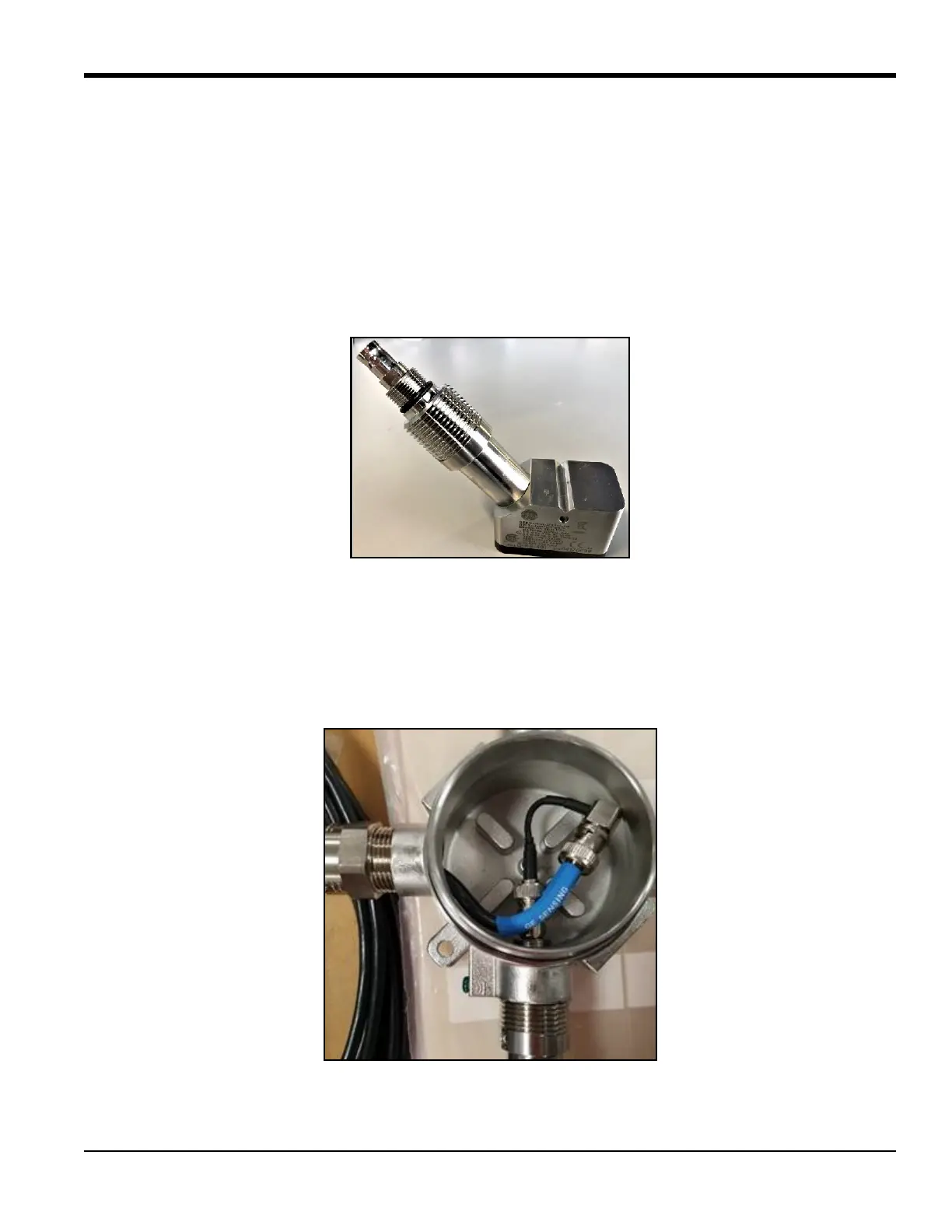
with the pipe because this is where the ultrasonic signal is emitted. All BHGE transducers include a dimple,
depression as it is illustrated in Figure 22, drill point or slot on the opposite side of the transducer wedge
face, for use as a guide in aligning and securing the transducer. In addition, some transducers have scribe
marks on the side to assist in setting the transducer spacing. Figure 17 below shows an example of the
dimple and scribe marks on the transducers.
Figure 17: Transducer Samples
To mount the transducers into a clamping fixture, complete the following steps:
1. To ensure that the minimum bend radius of the cable is met, the cable adapter is added in series with
the transducer cable assembly and the transducer. Connect the transducer cables to the BNC
connectors on the transducers, ensuring that the labels on the cables match with the transducers. For
example, the cable labeled 'downstream' must be connected to the downstream transducer.
Figure 18: Transducer Cable Connection with Cable Jumper, PN133M7313-03

 Loading...