PanaFlow™ LC User’s Manual 129
Appendix F. HART Communication
Appendix F. HART Communication
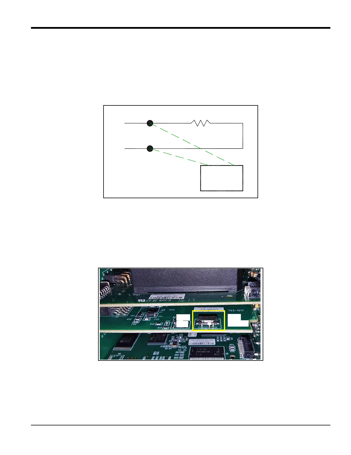
F.1 Wiring the XMT1000 to the HART Communicator
When connecting a HART communicator to the wiring terminals on the XMT1000 electronics terminal
board, the circuit must be terminated in an appropriate resistive load, as shown in Figure 123 below. The
HART communicator is connected in parallel with that load.
Figure 123: Wiring Diagram for HART Communication
F.2 HART Write Mode Switch
The XMT1000 HART circuit includes a slide switch which can be used to disable write access to the
instrument via HART. This slide switch (pictured in Figure 124 below) is designed to lock out HART
configuration access for those customers who require this extra level of security. With the Write Mode switch
pushed to the right, the HART circuit is in write enabled mode.
Figure 124: HART Circuit Write Mode Switch
Note: The following sections of this Appendix provide menu maps for programming the XMT1000 via HART
communication. To make programming changes through HART, the HART circuit must be set to Write Enabled
mode. Attempting to write to a device in Read Only mode will cause the device to indicate that the meter is in
Write-Protect mode.
Hart
Communicator
250 ohm
+
-

 Loading...