PanaFlow™ LC User’s Manual 43
Chapter 3. Programming
3.5.2 Standard Analog Output
The XMT1000 has one Analog Output and one Digital Output in Standard configuration.
3.5.2a Setting up Analog Output
The XMT1000 meter has one Analog Output in standard configuration. For additional Analog outputs
Optional I/O boards may be purchased. Use steps as in section “Log-in and Primary Pages” to navigate to the
Input/Output settings page.
1. Then highlight [Analog Output (Std)] and press [ENTER].
2. If you do not wish to connect an Analog Output, you should turn Analog Output selection to OFF.
3. If you are connecting an Analog Output, choose 4-20mA option. The Figure 57 below, shows the
options available.
4. Select the Measurement to be sent out on the 4-20mA output, followed by the [Base Value] and
[Full Value] selection. Refer Table 3 to see measurement options available for Analog output.
5. Select [Error Handling]. Refer to section 3.5.2.2 to choose an option that suits your needs.
3.5.2b Understanding the Error Handling Option
The following Table 4 shows the response to each of the Error Handling options. For a multi-channel meter,
the [Path Error Handling] set to ON (see Figure 70) changes the Output response. See Table 5 for Analog
Output response with [Path Error Handling] set to ON.
Note: Table 5 assumes Composite Actual Volumetric is chosen as Measurement for Analog Output.
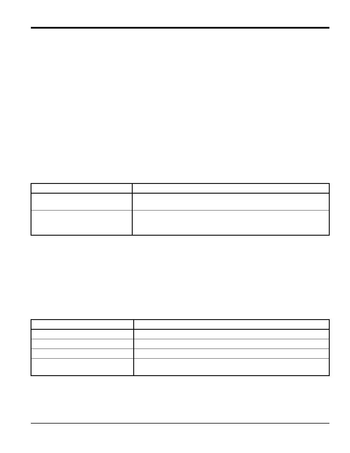
Table 3: Measurement Options for Analog output
Measurement Channel Measurement Options for Analog Output
Composite Velocity, Actual Volumetric, Standard Volumetric, Mass Flow, Average
Volumetric Flow Rate, Sound speed, Reynolds#
Channel x Velocity, Actual Volumetric, Standard Volumetric, Mass Flow, Average
Volumetric Flow rate, Sound speed, Standard Deviation of Gain, Gain
and SNR
Table 4: Analog Output Error Handling options
Option Output Response
Low Forces Output to 4mA on error
High Forces Output to 20mA on error
Hold Holds the last “good” reading
Other Enables the user to enter a value between 4mA and 20mA, to be
output during an error

 Loading...