EasyManuals Logo

GE Baker Hughes PanaFlow LC XMT1000 User Manual

GE Baker Hughes PanaFlow LC XMT1000
190 pages
To Next Page IconTo Next Page
To Previous Page IconTo Previous Page
Page #39 background imageLoading...
Page #39 background image
PanaFlow™ LC User’s Manual 25
Chapter 2. Installation
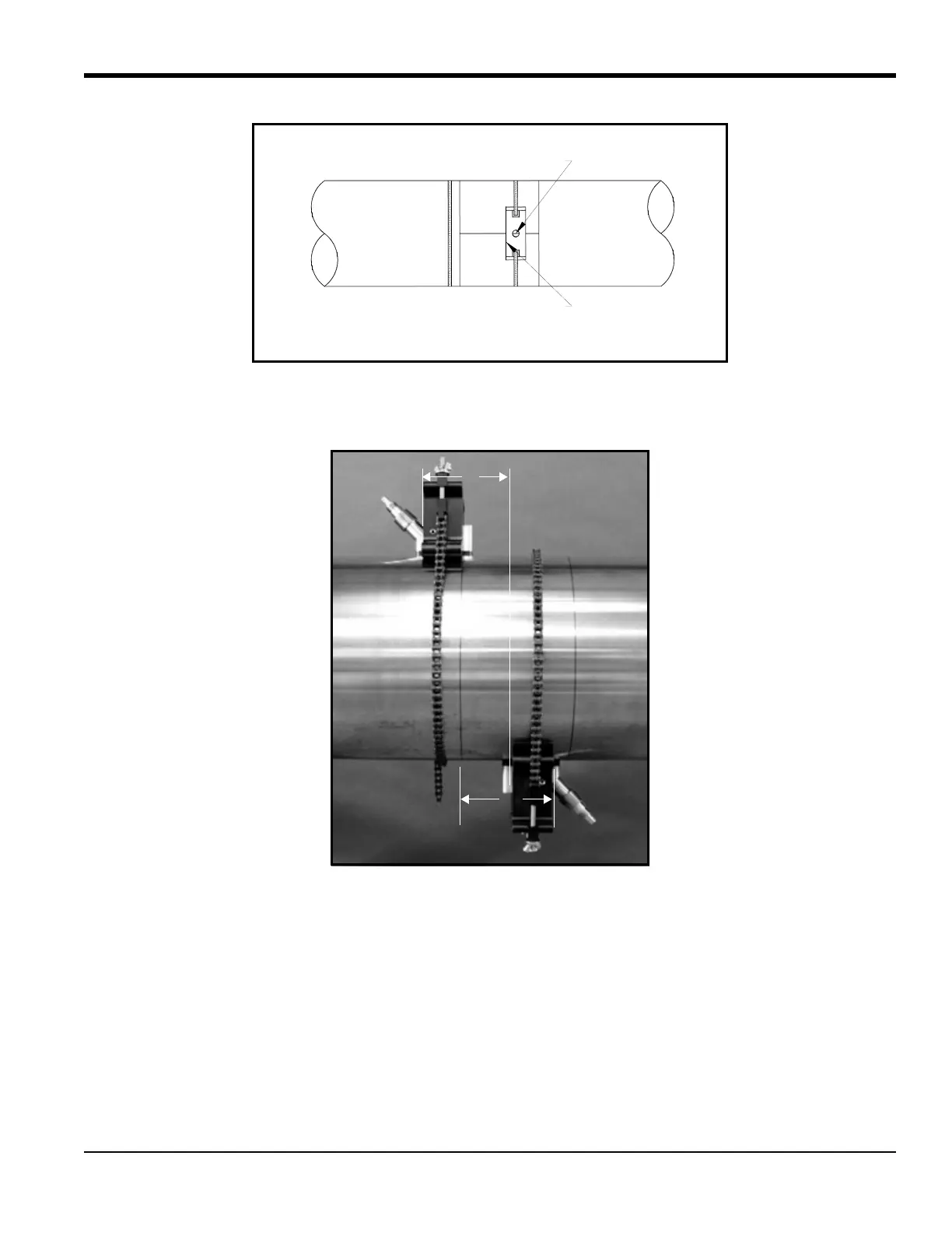
Figure 36: Line Up Rear Edge of Bracket with 180° Scribe Line
The spacing should now appear similar to that in Figure 37 below.
Figure 37: CFG-PI Fixture with Calculated Spacing
2.9.4 Installing the Transducers
1. Check to be sure the second CFG-PI holder bracket is correctly positioned.
2. Apply a bead of CPL-16 couplant 6 mm (0.25 in.) wide on each transducer face (see Figure 38 below).
Mark on Opposite Scribe Line
Rear Edge of Second Block
S
S

Table of Contents

Questions and Answers:

Question and Answer IconNeed help?

Do you have a question about the GE Baker Hughes PanaFlow LC XMT1000 and is the answer not in the manual?

GE Baker Hughes PanaFlow LC XMT1000 Specifications

General IconGeneral
BrandGE
ModelBaker Hughes PanaFlow LC XMT1000
CategoryMeasuring Instruments
LanguageEnglish

Related product manuals