 Loading...
Do you have a question about the GE Baker Hughes PanaFlow LC XMT1000 and is the answer not in the manual?
| Category | Measuring Instruments |
|---|---|
| Accuracy | ±0.5% of reading |
| Pipe Size Range | 2 to 48 inches |
| Temperature Range | -40 to 150°C (-40 to 302°F) |
| Outputs | 4-20 mA |
| Enclosure | NEMA 4X (IP66) |
Overview of the PanaFlow LC flowmeter's capabilities and intended use.
Explains the transit-time flow measurement principle used by the PanaFlow LC.
Provides general information for mechanical and electrical installation of the PanaFlow LC.
Instructions for inspecting and unpacking the PanaFlow LC system components.
Recommendations for selecting an optimal installation location for performance.
Describes methods for mounting transducers using various clamping fixtures.
Explains how to determine the number of signal paths for accurate flow measurement.
Important considerations and recommendations prior to fixture installation.
Guidelines for mounting transducers into clamping fixtures and connecting cables.
Instructions for installing the V Series clamping fixture and its transducers.
Detailed steps for installing the PI fixture and its associated transducers.
Information on connecting the XMT1000 transmitter module's electrical connections.
Guide for wiring the transducers to the junction boxes for the PanaFlow LC system.
Overview of the PanaFlow XMT1000 flow transmitter's programming features.
Describes the Human-Machine Interface (HMI) and its keys for programming.
Explains the function of the power and error indicator lights on the device.
Details the default passcodes and security levels for accessing menus.
Guides the user through logging into the meter and navigating primary pages.
Allows configuration of system-wide settings like units and meter parameters.
Configuration options for digital and analog inputs/outputs and communication ports.
Explains how to select programming options for accurate flow measurements.
An overview of troubleshooting procedures for the XMT1000 flow meter.
Details the classification and meaning of XMT1000 error codes.
Troubleshooting specific flow-related errors (E-Errors) with causes and actions.
Diagnosing measurement issues related to fluid properties or pipe conditions.
Identifies potential issues with transducers and provides troubleshooting steps.
Information on accessing test points on the main board for service diagnostics.
Explains system errors (S-Errors) related to the flow subsystem.
Details communication errors (C-Errors) between system components.
Lists errors originating from the transmitter subsystem and their solutions.
Describes errors related to the optional Input/Output modules.
Provides diagnostic parameters for system health and troubleshooting.
Guidance on maintaining and inspecting transducers for optimal operation.
Details the operational characteristics and performance specifications of the flowmeter.
Information regarding the electronic components, enclosures, and interfaces.
Explains the structure and meaning of the product's part numbers.
Instructions for installing and using the Universal Clamping Fixture (UCF).
Installation guide for the General Clamping Fixture (GCF) for permanent transducer mounting.
Procedures for installing and using the Magnetic Clamping Fixture (MCF) for transducer mounting.
Section for recording electronics data, including service history.
Table for logging initial measurement settings after meter installation.
Fields for recording initial and current diagnostic parameter values.
Table detailing the Modbus input registers for accessing device data.
Introduction to CE Mark compliance requirements for the PanaFlow LC.
Specifies wiring requirements for achieving CE Mark compliance.
Instructions for wiring the XMT1000 to a HART communicator.
Explains the function of the HART write mode switch for security.
Provides HART menu maps for programming the XMT1000.
Lists the measurements that can be configured and accessed via HART communication.
Introduction to Wireless HART communication protocols for field devices.
Steps for installing and configuring the XMT1000 with a Masoneilan VECTOR adaptor.
Introduction to Fieldbus communication protocols for process control systems.
Covers network configuration, terminators, field devices, and host for Fieldbus setup.
Details general, physical, and communication specifications for Foundation Fieldbus.
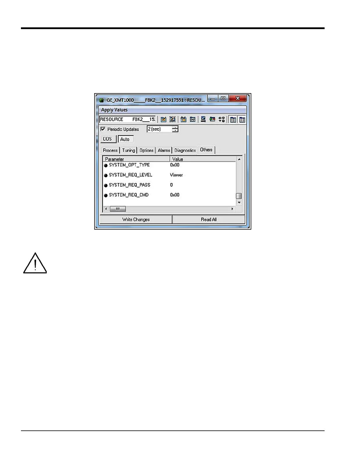
Provides information on the XMT1000 Foundation Fieldbus implementation, including revisions and passwords.
Describes parameters and selectable units available in the XMIT Transducer Block.
Details measurement values and programmable parameters common to all three paths.
Lists measurements available for configuration over Foundation Fieldbus.
Shows measurement values and parameters for individual channels (CH1, CH2, CH3).
Describes the Analog Input (AI) block for signal conditioning and data processing.
Explains the PID function block for programmable control algorithms.
How the flow meter publishes error status and quality information over Fieldbus.
Instructions for enabling simulation mode to test FF implementation without real data.
Provides solutions for common Fieldbus problems with the XMT1000.
Information on using the DPI620 FF calibrator for diagnostics.