Chapter 2. Installation
20 PanaFlow™ LC User’s Manual
Figure 25: Installing Nuts onto the Fixture
2.8.2 Installing the Transducers
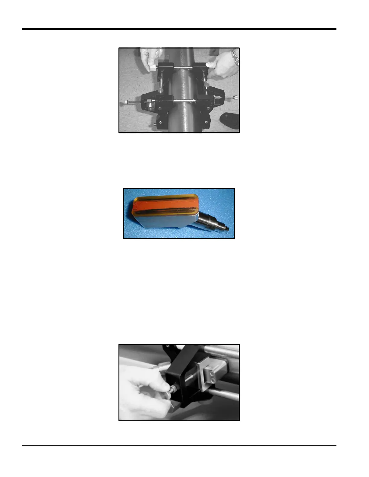
1. Apply a bead of coupling 6 mm (0.25 in.) wide along the entire length of each transducer face, as
shown in Figure 26 below.
Figure 26: Couplant on Transducer Face
Note: Do not slide the transducer with couplant along the surface of the pipe when mounting the transducer.
2. Set the first mounting block (either left edge or right edge) at a convenient number on the scale, such
as 2 in. or 5 cm. Install the first transducer with the BNC connector pointing away from the center of
the V block fixture. Tighten the transducer mounting thumbscrew onto the slider, which in turn
applies pressure to the transducer. Use a handtight grip to set the transducer in contact with the pipe,
as shown in Figure 27 below. Use a wrench to tighten the backing nut to prevent loosening due to
vibration and thermal expansion.
IMPORTANT: Do not use a wrench or pliers on the thumbscrew.
Figure 27: Installing the First Transducer

 Loading...