PanaFlow™ LC User’s Manual 27
Chapter 2. Installation
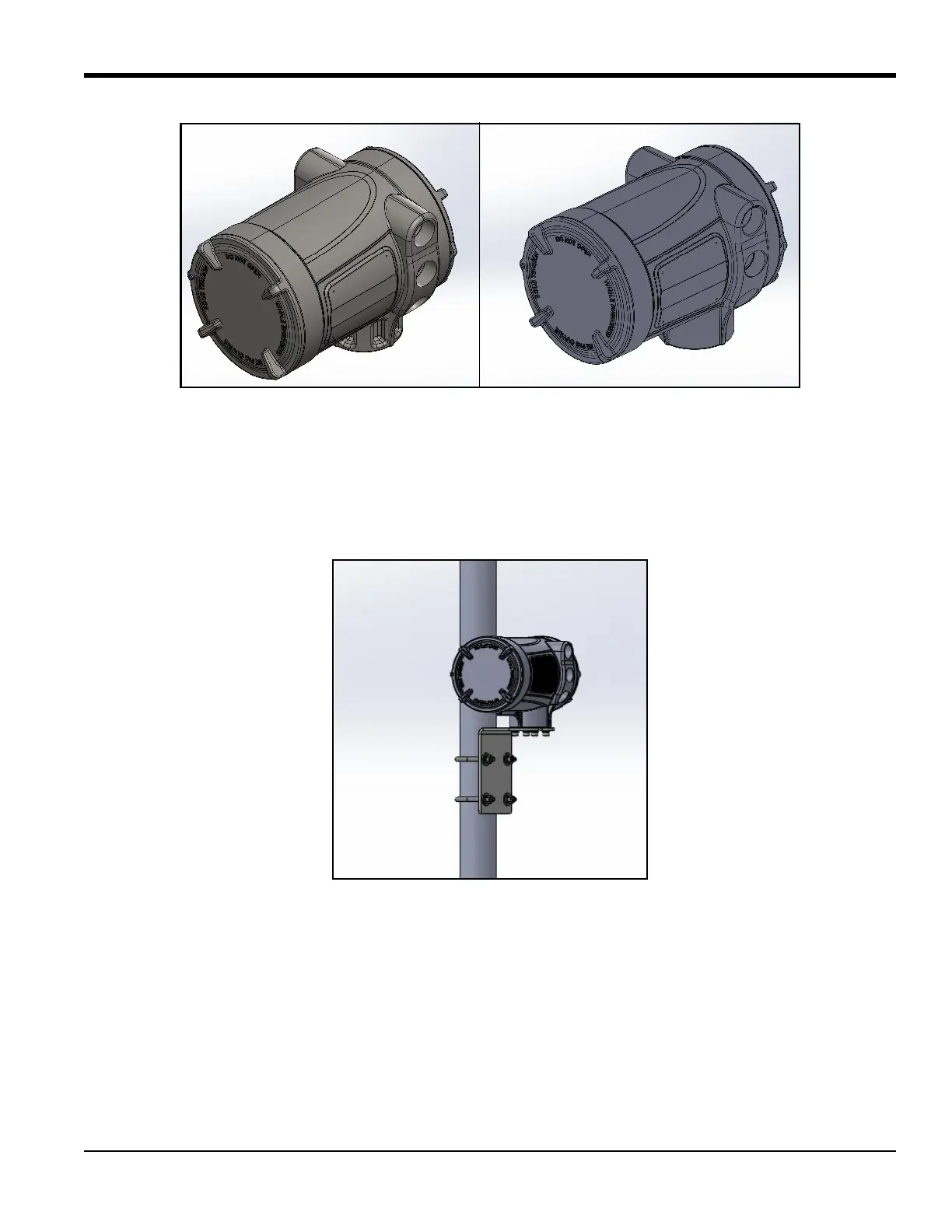
Figure 39: LEFT: Stainless Steel Junction Box, RIGHT: Aluminum Junction Box
2.11.1 Installing the Junction Box
Mount the aluminum (5lbs) or stainless steel (15lbs) junction box using the included mounting plate to a wall
(hardware supplied by end user) or a
2 inch pipe (hardware supplied with J-box). See Figure 40 for reference.
Figure 40: Aluminum J-box mount to 2" pipe using supplied hardware kit
(Stainless Steel install will be identical)
2.11.2 Single Channel Set up
Components of a single channel PanaFlow LC will be a meter head, two transducer cables and a set of
transducers and clamping fixtures. Mount meter head to a two inch post using included hardware or another
location following local electrical and building codes.
Install transducers as mentioned in Sections 2.7 through Section 2.9. Prepare to wire transducer cables.
Note: US/ Canada installations will be required to provide conduit per their particular location. European
installations will include armored cable.

 Loading...