3.4.2 RING MAIN ARRANGEMENTS
E00604
Load
Load
Load
Load
Load
Load
A
B
C
D
E
F
Source
2.1s
2.1s
0.1s
0.1s
1.7s
1.7s
0.5s
0.5s
1.3s
1.3s
0.9s
0.9s
6
7
67
67
67
67
67
67
67
67
67
51 51
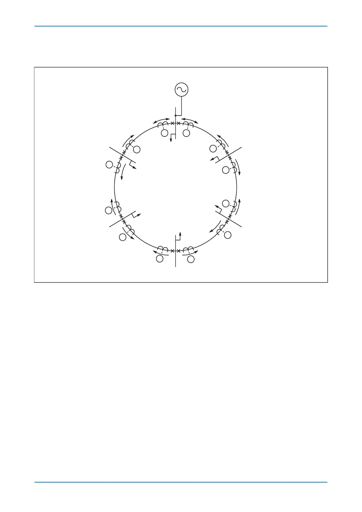
Figure 37: Typical ring main with associated overcurrent protection
In a ring main arrangement, curr
ent may flow in either direction through the various device locations, therefore
directional overcurrent devices are needed to achieve correct discrimination.
The normal grading procedure for overcurrent devices protecting a ring main circuit is to consider the ring open at
the supply point and to grade the devices first clockwise and then anti-clockwise. The arrows shown at the various
device locations depict the direction for forward operation of the respective devices (i.e. the directional devices are
set to look into the feeder that they are protecting).
The diagram shows typical time settings (assuming definite time co-ordination is used), from which it can be seen
that any faults on the interconnections between stations are cleared discriminatively by the devices at each end of
the feeder.
Any of the overcurrent stages may be configured to be directional and co-ordinated, but bear in mind that IDMT
characteristics are not selectable on all the stages.
3.4.3 SETTING GUIDELINES
Standard principles should be applied in calculating the necessary current and time settings. The example detailed
below shows a typical setting calculation and describes how the settings are applied.
P14x Chapter 6 - Curr
ent Protection Functions
P14xEd1-TM-EN-1 103
 Loading...


