3.2 OVERVOLTAGE PROTECTION LOGIC
V00804
VA
V>1 Voltage Set
V>1 Time Delay
V >1 Trip A/AB
V>1 Start A/AB
&
1
&
&
&
1
&
&
1
1
V>1 Start
V>1 Trip
V> Operate mode
Any Phase
Three Phase
V> Measur't Mode
VAB
&
VB
V>1 Voltage Set
V>1 Time Delay
V>1 Trip B/BC
V>1 Start B/BC
V> Measur't Mode
VBC
&
VC
V>1 Voltage Set
V>1 Time Delay
V>1 Trip C/CA
V>1 Start C/CA
V> Measur't Mode
VCA
&
V>1 Timer Block
Notes: This diagram does not show all stages . Other stages follow similar principles.
VTS Fast Block only applies for directional models .
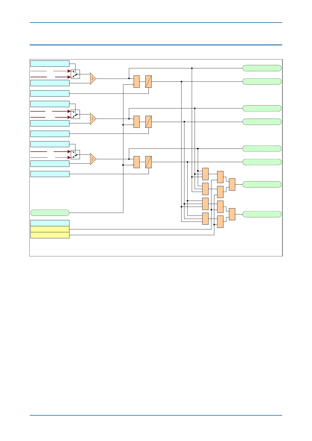
Figure 111: Overvoltage - single and three phase tripping mode (single stage)
The Ov
ervoltage protection function detects when the voltage magnitude for a certain stage exceeds a set
threshold. If this happens a Start signal, signifying the "Start of protection", is produced. This Start signal can be
blocked by the VTS Fast Block signal. This start signal is applied to the timer module to produce the Trip signal,
which can be blocked by the overvoltage timer block signal (V>(n) Timer Block). For each stage, there are three
Phase overvoltage detection modules, one for each phase. The three Start signals from each of these phases are
OR'd together to create a 3-phase Start signal (V>(n) Start), which can then be activated when any of the three
phases start (Any Phase), or when all three phases start (Three Phase), depending on the chosen V> Operate Mode
setting.
The outputs of the timer modules are the trip signals which are used to drive the tripping output relay. These
tripping signals are also OR'd together to create a 3-phase Trip signal, which are also controlled by the V> Operate
Mode setting.
If any one of the above signals is low, or goes low before the timer has counted out, the timer module is inhibited
(effectively reset) until the blocking signal goes high.
Chapter 10 - Voltage Protection Functions P14x
214 P14xEd1-TM-EN-1
 Loading...


