3 MOUNTING THE DEVICE
The products are dispatched either individually or as part of a panel or rack assembly.
Individual products ar
e normally supplied with an outline diagram showing the dimensions for panel cut-outs and
hole centres.
The products are designed so the fixing holes in the mounting flanges are only accessible when the access covers
are open.
If you use a P991 or MMLG test block with the product, when viewed from the front, position the test block on the
right-hand side of the associated product. This minimises the wiring between the product and test block, and
allows the correct test block to be easily identified during commissioning and maintenance tests.
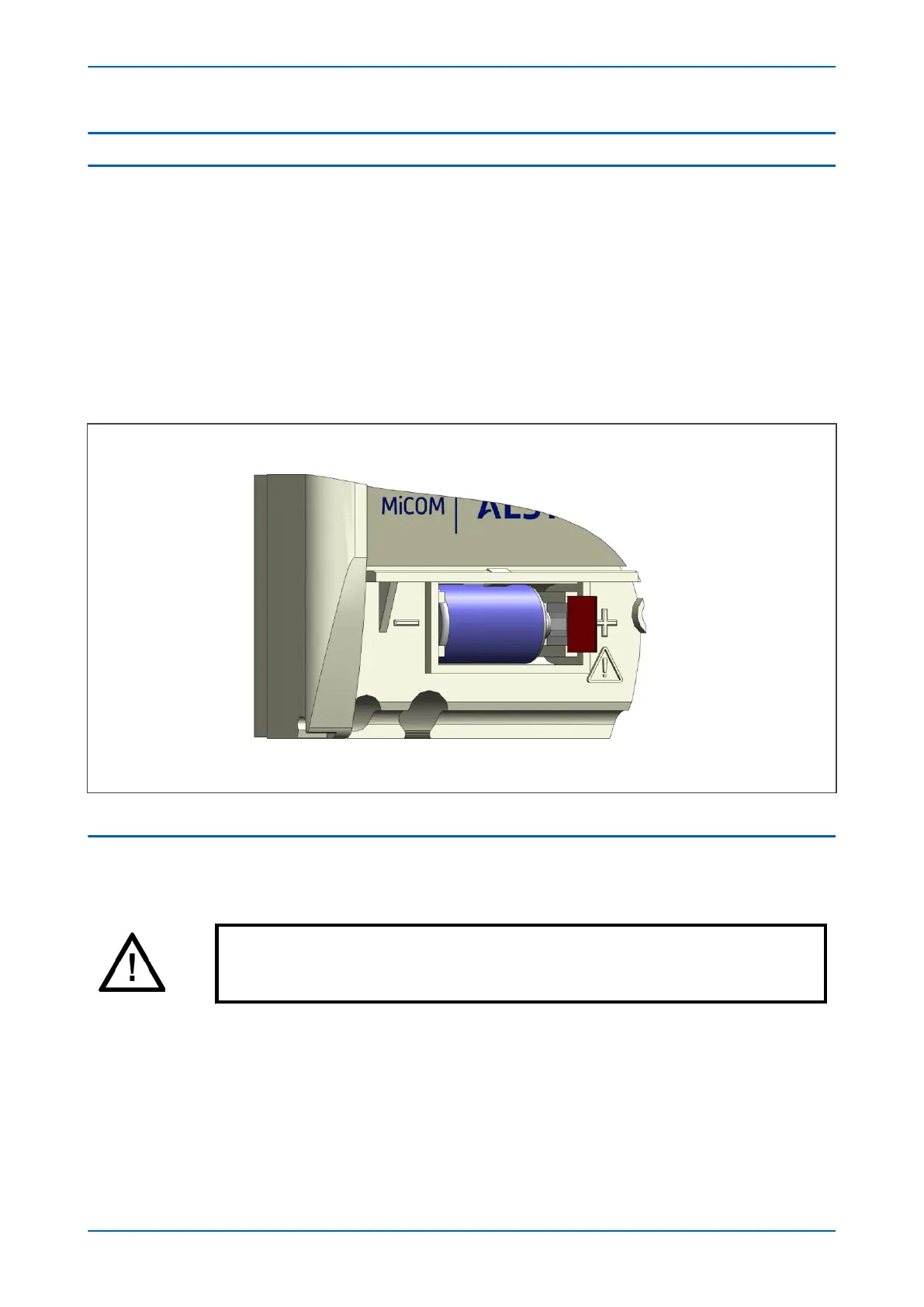
If you need to test the product for correct operation during installation, open the lower access cover, hold the
battery in place and pull the red tab to remove the battery isolation strip.
Figure 212: Location of battery isolation strip
3.1 FLUSH PANEL MOUNTING
Panel-mounted devices are flush mounted into panels using M4 SEMS Taptite self-tapping screws with captive
3 mm thick washer
s (also known as a SEMS unit).
Caution:
Do not use conventional self
-tapping screws, because they have larger heads and could
damage the faceplate.
Alternatively, you can use tapped holes if the panel has a minimum thickness of 2.5 mm.
For applications where the pr
oduct needs to be semi-projection or projection mounted, a range of collars are
available.
If several products are mounted in a single cut-out in the panel, mechanically group them horizontally or vertically
into rigid assemblies before mounting in the panel.
P14x Chapter 20 - Installation
P14xEd1-TM-EN-1 477
 Loading...


