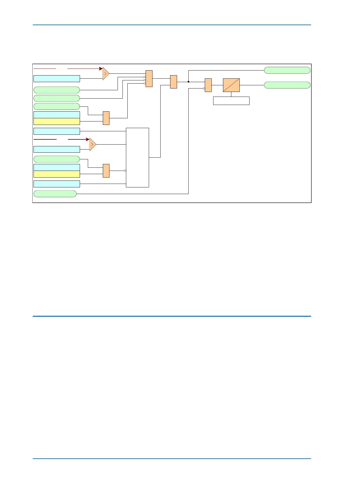
9.4.1 DIRECTIONAL NEGATIVE SEQUENCE OVERCURRENT LOGIC
I2>1 Tmr Blk
V00608
I2>1 Start
I2>1 Trip
CTS Block
I2> Blocking
2H Blocks I2>1
I2>1 Current Set
&
IDMT/DT
Timer Settings
&
&
I2> Inhibit
I2H Any Start
&
VTS Slow Block
I2> Blocking
VTS Blocks I2>1
I2> V2pol Set
Directional
check
I2>1 Direction
&
Note : This diagram does not show all stages . Other stages follow
similar principles.
I2> Char Angle
I2
V2
Figure 47: Negative Sequence Overcurrent logic - directional operation
Directionality is achiev
ed by comparing the angle between the negative phase sequence voltage and the negative
phase sequence current. The element may be selected to operate in either the forward or reverse direction. A
suitable characteristic angle setting (I2>Char Angle) is chosen to provide optimum performance. This setting
should be set equal to the phase angle of the negative sequence current with respect to the inverted negative
sequence voltage (–V2), in order to be at the centre of the directional characteristic.
For the negative phase sequence directional elements to operate, the device must detect a polarising voltage
above a minimum threshold, I2> V2pol Set. This must be set in excess of any steady state negative phase
sequence voltage. This may be determined during the commissioning stage by viewing the negative phase
sequence measurements in the device.
When the element is selected as directional (directional devices only), a VTS Block option is available. When the
relevant bit is set to 1, operation of the Voltage Transformer Supervision (VTS) will block the stage. When set to 0,
the stage will revert to non-directional.
9.5 APPLICATION NOTES
9.5.1 SETTING GUIDELINES (CURRENT THRESHOLD)
A negative phase sequence element can be connected in the primary supply to the transformer and set as
sensitiv
ely as r
equired to protect for secondary phase-to-earth or phase-to-phase faults. This function will also
provide better protection than the phase overcurrent function for internal transformer faults. The NPS overcurrent
protection should be set to coordinate with the low-side phase and earth elements for phase-to-earth and phase-
to-phase faults.
The current pick-up threshold must be set higher than the negative phase sequence current due to the maximum
normal load imbalance. This can be set practically at the commissioning stage, making use of the measurement
function to display the standing negative phase sequence current. The setting should be at least 20% above this
figure.
Where the negative phase sequence element needs to operate for specific uncleared asymmetric faults, a precise
threshold setting would have to be based on an individual fault analysis for that particular system due to the
complexities involved. However, to ensure operation of the protection, the current pick-up setting must be set
Chapter 6 - Current Protection Functions P14x
118 P14xEd1-TM-EN-1
 Loading...


