14 BLOCKED OVERCURRENT PROTECTION
With Blocked Overcurrent schemes, you connect the start contacts from downstream IEDs to the timer blocking
inputs of upstream IEDs. This allows identical curr
ent and time settings to be used on each of the IEDs in the
scheme, as the device nearest to the fault does not receive a blocking signal and so trips discriminatively. This type
of scheme therefore reduces the number of required grading stages, and consequently fault clearance times.
The principle of Blocked Overcurrent protection may be extended by setting fast-acting overcurrent elements on
the incoming feeders to a substation, which are then arranged to be blocked by start contacts from the devices
protecting the outgoing feeders. The fast-acting element is thus allowed to trip for a fault condition on the busbar,
but is stable for external feeder faults due to the blocking signal.
This type of scheme provides much reduced fault clearance times for busbar faults than would be the case with
conventional time-graded overcurrent protection. The availability of multiple overcurrent and earth fault stages in
the General Electric IEDs allows additional time-graded overcurrent protection for back-up purposes.
14.1 BLOCKED OVERCURRENT IMPLEMENTATION
Blocked Overcurrent schemes are implemented using the PSL. The start outputs, available from each stage of the
over
current and earth fault elements (including the sensitive earth fault element) can be mapped to output relay
contacts. These outputs can then be connected to the relevant timer block inputs of the upstream IEDs via opto-
inputs.
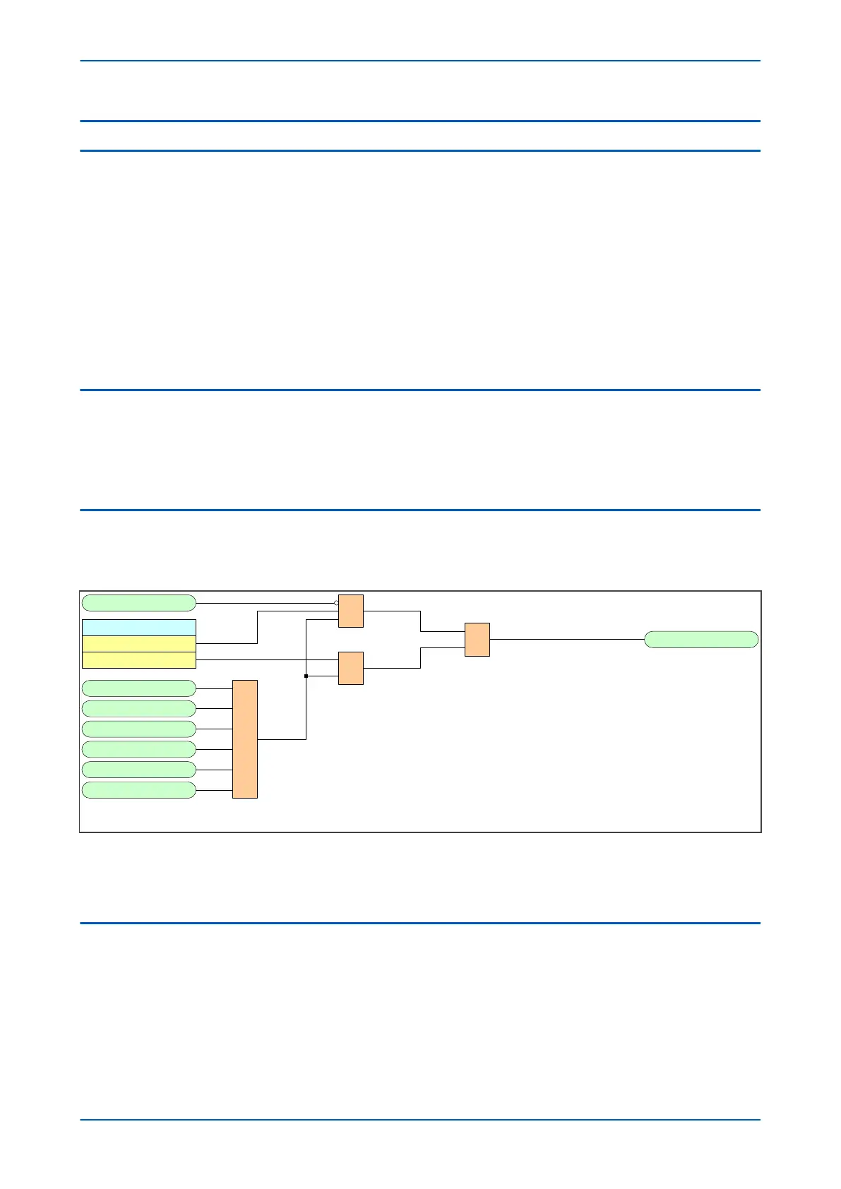
14.2 BLOCKED OVERCURRENT LOGIC
To facilitate the implementation of blocked overcurrent schemes, the device provides the following logic to provide
a Blocked O
vercurrent Start signal I> BlockStart:
Remove I > Start
Enabled
&
CB Fail Alarm
Disabled
&
1
I>1 Start
I>2 Start
I>3 Start
I>4 Start
I>5 Start
I>6 Start
1 I> BlockStart
V00648
Figure 72: Blocked Overcurrent logic
The I> BlockStar
t signal is derived from the logical OR of the phase overcurrent start outputs. This output is then
gated with the CB Fail Alarm DDB signal and the setting Remove I> Start setting.
14.3 BLOCKED EARTH FAULT LOGIC
To facilitate the implementation of blocked overcurrent schemes, the device provides the following logic to provide
the Blocked Ear
th Fault signal IN/SEF>Blk Start:
Chapter 6 - Current Protection Functions P14x
146 P14xEd1-TM-EN-1
 Loading...


