(c)
I = 3I
f A
(b)
Ia = √3I
A
V
Cf
V = √3V
Af A
V
A
I
A
(a)
E00821
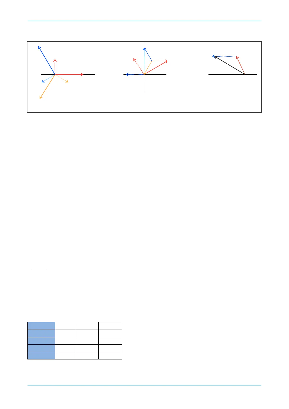
Figure 118: Condenser bushing system vectors
In the figure abov
e:
(a) Shows three healthy voltages, three capacitor currents that lead their respective voltages by 90º and sum to
zero,
(b) Shows B phase earthed, A and C voltages are √3 times their healthy magnitude & at 60º to each other, giving
correspondingly altered capacitor currents Ia and Ic.
The vector sum of the A & C phase capacitor currents is:
I
f
= √3 x Ia,
= √3 x √3 x I
A
,
= 3 x I
A
Therefore, the total fault current I
f
equals three times a single capacitor healthy condition current I
A
.
(c) Shows the vector sum of the fault condition I
f
.
Therefore, I
f
is the current which will flow in the Neutral Displacement Relay under fault conditions (neglecting the
impedance of the relay itself).
For example, for a 60pF capacitor on a 33kV system, the single capacitor healthy condition current I
A
is given by:
I
A
= V
A
/ X
C
= V
A
/ (1/2pfC)
=
33 x 10
3
/ (1/(2 x p x 50 x 60 x 10
-12
))
√3
= 0.359mA
Therefor
e, the total fault current which would flow in an NVD relay (neglecting the impedance of the relay itself):
I
f
= 3 x 0.359 = 1.08mA
The table below shows the total fault current I
f
for a 60pF capacitor, and also I
f
for a 90pF capacitor, and for a
150pF capacitor.
C (pF) 60.00 90.00 150.00
Xc (MΩ) 53.08 35.39 21.23
VA (kV) 19.00 19.00 19.00
IA (mA) 0.359 0.539 0.898
If (mA) 1.08 1.62 2.69
P14x Chapter 10 - Voltage Protection Functions
P14xEd1-TM-EN-1 223
 Loading...


