V00670
Current p.u.
(x full load)
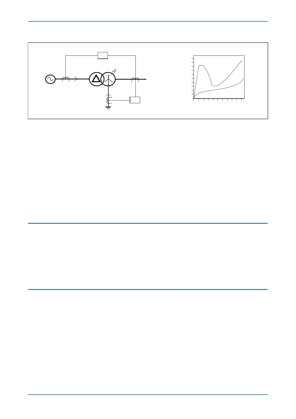
Source
Fault position from neutral
(Solid earthing)
20% 40% 60% 80% 100%
87
I
S
I
F
I
F
64
I
F
I
S
10
8
6
4
2
Figure 89: REF Protection for solidly earthed system
In this case, the fault current I
F
is dependent on:
● The leakage r
eactance of the winding
● The impedance in the fault path
● The fault point voltage (which is governed by the fault location)
In this case, the value of fault current (I
F
) varies with the fault location in a complex manner.
A restricted earth fault element is connected to measure I
F
directly. This provides very sensitive earth fault
protection.
For solidly earthed systems, the operating current for the transformer differential protection is still significant for
faults over most of the winding. For this reason, independent REF protection may not have been previously
considered, especially where an additional device would have been needed. But with this product, it can be
applied without extra cost.
2.3 THROUGH FAULT STABILITY
In an ideal world, the CTs either side of a differentially protected system would be identical with identical
characteristics to avoid cr
eating a differential current. However, in reality CTs can never be identical, therefore a
certain amount of differential current is inevitable. As the through-fault current in the primary increases, the
discrepancies introduced by imperfectly matched CTs is magnified, causing the differential current to build up.
Eventually, the value of the differential current reaches the pickup current threshold, causing the protection
element to trip. In such cases, the differential scheme is said to have lost stability. To specify a differential scheme’s
ability to restrain from tripping on external faults, we define a parameter called ‘through-fault stability limit’, which
is the maximum through-fault current a system can handle without losing stability.
2.4 RESTRICTED EARTH FAULT TYPES
There are two different types of Restricted Earth Fault; Low Impedance REF (also known as Biased REF) and High
Impedance REF. Each method compensates for the effect of thr
ough-fault errors in a different manner.
With Low Impedance REF, the through-fault current is measured and this is used to alter the sensitivity of the REF
element accordingly by applying a bias characteristic. So the higher the through fault current, the higher the
differential current must be for the device to issue a trip signal, Often a transient bias component is added to
improve stability during external faults.
Low impedance protection used to be considered less secure than high impedance protection. This is no longer
true as numerical IEDs apply sophisticated algorithms to match the performance of high-impedance schemes.
Some advantages of using Low Impedance REF are listed below:
● There is no need for dedicated CTs. As a result CT cost is substantially reduced.
● The wiring is simpler as it does not require an external resistor or Metrosil.
Chapter 7 - Restricted Earth Fault Protection P14x
166 P14xEd1-TM-EN-1
 Loading...


