4 VOLTAGE DEPENDENT OVERCURRENT ELEMENT
An overcurrent protection scheme is co-ordinated throughout a system such that cascaded operation is achieved.
This means that if for some reason a downstr
eam circuit breaker fails to trip for a fault condition, the next
upstream circuit breaker should trip.
However, where long feeders are protected by overcurrent protection, the detection of remote phase-to-phase
faults may prove difficult due to the fact that the current pick-up of phase overcurrent elements must be set above
the maximum load current, thereby limiting the minimum sensitivity.
If the current seen by a local device for a remote fault condition is below its overcurrent setting, a voltage
dependent element may be used to increase the sensitivity to such faults. As a reduction in system voltage will
occur during overcurrent conditions, this may be used to enhance the sensitivity of the overcurrent protection by
reducing the pick up level.
Voltage dependent overcurrent devices are often applied in generator protection applications in order to give
adequate sensitivity for close up fault conditions. The fault characteristic of this protection must then co-ordinate
with any of the downstream overcurrent devices that are responsive to the current decrement condition. It
therefore follows that if the device is to be applied to an outgoing feeder from a generator station, the use of
voltage dependent overcurrent protection in the feeder device may allow better co-ordination with the Voltage
Dependent device on the generator.
4.1 VOLTAGE DEPENDENT OVERCURRENT PROTECTION IMPLEMENTATION
Voltage Dependent Overcurrent Protection (VDep OC) is set in the OVER
CURRENT column of the relevant settings
group, under the sub-heading V DEPENDANT O/C.
The function is available for stages 1, 2 and 5 of the main overcurrent element. When VDep OC is enabled, the
overcurrent threshold setting is modified when the voltage falls below a set threshold.
If voltage dependant overcurrent operation is selected, the element can be set in one of two modes, voltage
controlled overcurrent or voltage restrained overcurrent.
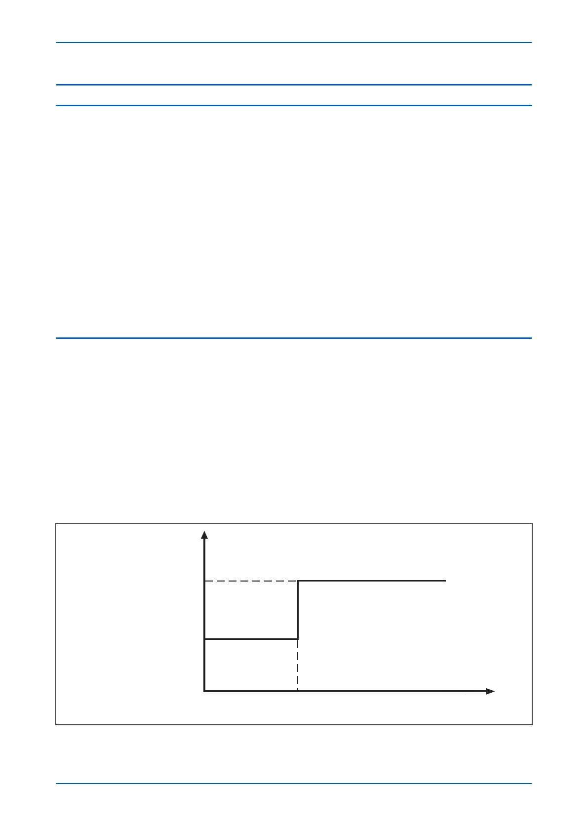
4.1.1 VOLTAGE CONTROLLED OVERCURRENT PROTECTION
In Voltage Controlled Operation (VCO) mode of operation, the under voltage detector is used to produce a step
change in the curr
ent setting, when the v
oltage falls below the voltage setting V Dep OC V<1 Set. The operating
characteristic of the current setting when voltage controlled mode is selected is as follows:
E00642
Current pickup setting
K x Current pickup setting
Voltage threshold setting
Current
setting
Measured voltage
Figure 38: Modification of current pickup level for voltage controlled overcurrent protection
P14x Chapter 6 - Current Protection Functions
P14xEd1-TM-EN-1 105
 Loading...


