7 AVERAGE RATE OF CHANGE OF FREQUENCY PROTECTION
Owing to the complex dynamics of power systems, variations in frequency during times of generation-to-load
imbalance are highly non-linear
. Oscillations will occur as the system seeks to address the imbalance, resulting in
frequency oscillations typically in the order of 0.1 Hz to 1 Hz, in addition to the basic change in frequency.
The independent and frequency-supervised rate of change of frequency elements use an instantaneous
measurement of the rate of change of frequency, based on a 3-cycle, filtered, rolling average technique. Due to
the oscillatory nature of frequency excursions, this instantaneous value can sometimes be misleading, either
causing unexpected operation or excessive instability. For this reason, the device also provides an element for
monitoring the longer term frequency trend, thereby reducing the effects of non-linearity in the system.
Average Rate of Change of Frequency protection is also known as f+Df/Dt protection (note the upper-case "D").
7.1 AVERAGE R.O.C.O.F PROTECTION IMPLEMENTATION
The device provides nine independent stages of average rate of change of frequency protection. Each stage can
respond to either rising or falling fr
equency conditions. This depends on whether the frequency threshold is set
above or below the system nominal frequency. For example, if the frequency threshold is set above nominal
frequency, the rate of change of frequency setting is considered as positive and the element will operate for rising
frequency conditions. If the frequency threshold is set below nominal frequency, the setting is considered as
negative and the element will operate for falling frequency conditions.
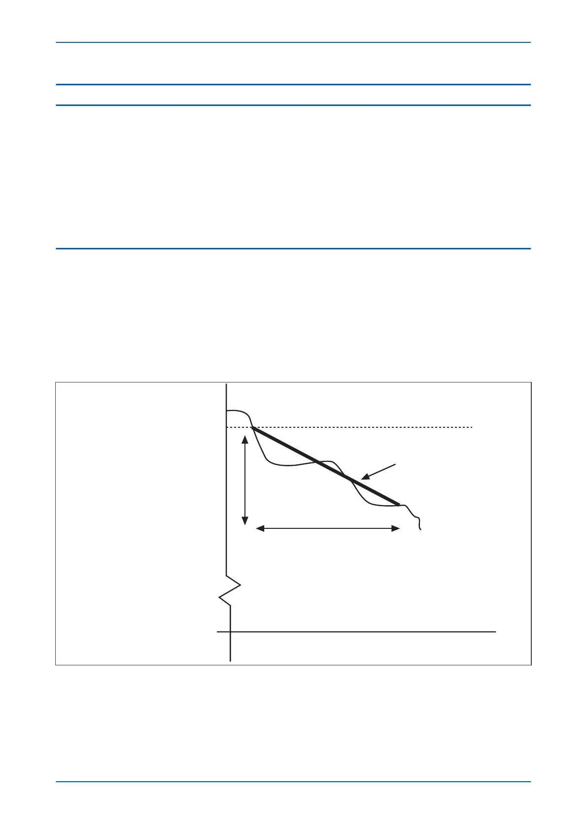
When the measured frequency crosses the supervising frequency threshold, a timer is initiated. At the end of this
time period, the frequency difference is evaluated and if this exceeds the setting, a trip output is given.
E00856
ΔF
Δt
f
True slope for the time Δt
f
Supervising frequency
t
Figure 132: Average rate of change of frequency characteristic
After time
∆
t, the element is blocked from further operation until the frequency recovers to a value above the
supervising frequency threshold. If the element has operated, the trip DDB signal will be ON until the frequency
recovers to a value above the supervising frequency threshold.
Chapter 11 - Frequency Protection Functions P14x
248 P14xEd1-TM-EN-1
 Loading...


