For each of the above registers a value of 0 represents the most recent stored record. The following registers can
be read to indicate the number
s of the various types of record stored.
● 30100: Number of stored records
● 30101: Number of stored fault records
● 30102: Number of stored maintenance records
Each fault or maintenance record logged causes an event record to be created. If this event record is selected, the
additional registers allowing the fault or maintenance record details will also become populated.
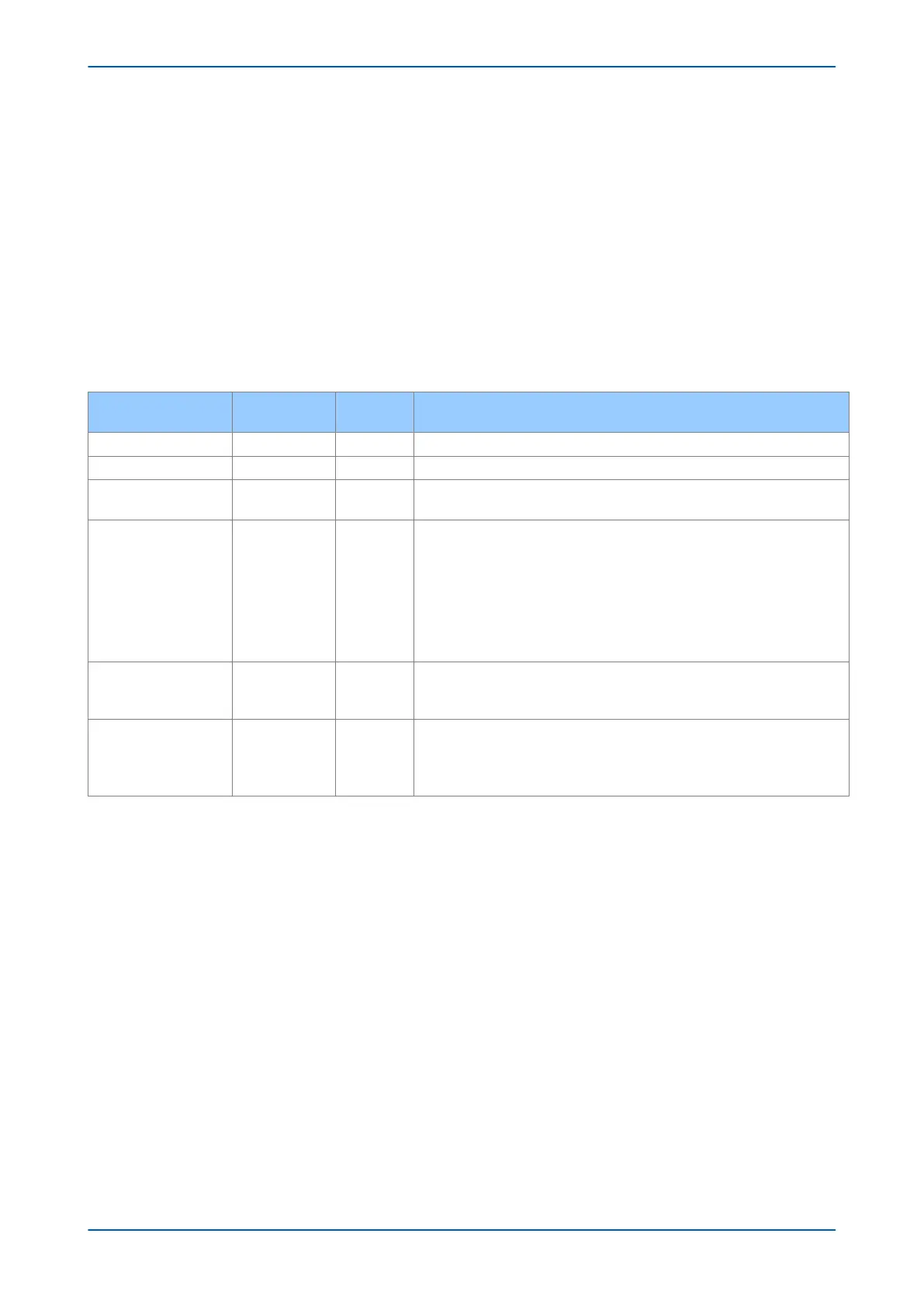
7.4.5.3 RECORD DATA
The location and format of the registers used to access the record data is the same whether they have been
selected using either automatic or manual extraction.
Event Description
MODBUS
Address
Length Comments
Time and Date
30103 4 See G12 data type description
Event Type 30107 1 See G13 data type description
Event Value 30108 2
Nature of value depends on event type. This will contain the status as a binary flag
for contact
, opto-input, alarm, and protection events.
MODBUS Address 30110 1
This indicates the MODBUS register address where the change occurred.
Alarm 30011
Relays 30723
Optos 30725
Pr
otection events – like the relay and opto addresses this will map onto the
MODBUS address of the appropriate DDB status register depending on which bit
of the DDB the change occurred. These will range from 30727 to 30785.
For platform events, fault events and maintenance events the default is 0.
Event Index 30111 1
This register will contain the DDB ordinal for protection events or the bit number
for alarm events. The dir
ection of the change will be indicated by the most
significant bit; 1 for 0 – 1 change and 0 for 1 – 0 change.
Additional Data Present 30112 1
0 means that there is no additional data.
1 means fault recor
d data can be read from 30113 to 30199 (number of registers
depends on the product).
2 means maintenance record data can be read from 30036 to 30039.
If a fault record or maintenance record is directly selected using the manual mechanism then the data can be read
from the r
egister ranges specified above. The event record data in registers 30103 to 30111 will not be available.
It is possible using register 40401(G6 data type) to independently clear the stored relay event/fault and
maintenance records. This register also provides an option to reset the device indications, which has the same
effect on the relay as pressing the clear key within the alarm viewer using the HMI panel menu.
7.4.6 DISTURBANCE RECORD EXTRACTION
The IED provides facilities for both manual and automatic extraction of disturbance records.
R
ecor
ds extracted over MODBUS from Px40 devices are presented in COMTRADE format. This involves extracting
an ASCII text configuration file and then extracting a binary data file.
Each file is extracted by reading a series of data pages from the IED The data page is made up of 127 registers,
giving a maximum transfer of 254 bytes per page.
The following set of registers is presented to the master station to support the extraction of uncompressed
disturbance records:
P14x Chapter 18 - Communications
P14xEd1-TM-EN-1 433
 Loading...


