sequence current to flow through the neutral line, resulting in uneven currents in the phases, which could cause
the protection to maloperate. By measuring this zer
o sequence current and placing it in parallel with the other
three, the currents are balanced, resulting in stable operation. Now only a fault inside the star winding can create
an imbalance sufficient to cause a trip.
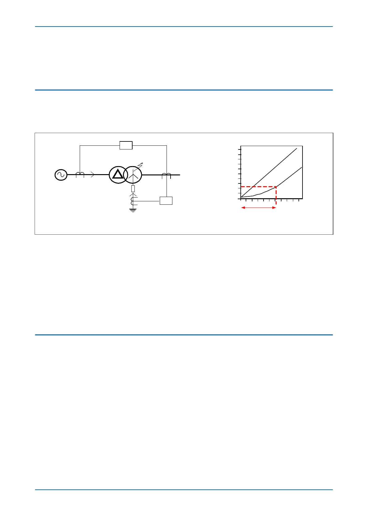
2.1 RESISTANCE-EARTHED STAR WINDINGS
Most distribution systems use resistance-earthed systems to limit the fault current. Consider the diagram below,
which depicts an earth fault on the star winding of a r
esistance-earthed Dyn transformer (Dyn = Delta-Star with
star-point neutral connection).
V00669
Source
Current p.u.
(x full load)
Fault position from neutral
(Impedance earthing)
20% 100%
Winding not protected
Pickup
1.0
87
64
I
S
I
F
I
F
I
S
0.2
I
F
Figure 88: REF Protection for resistance-earthed systems
The value of fault curr
ent (I
F
) depends on two factors:
● The value of earthing resistance (which makes the fault path impedance negligible)
● The fault point voltage (which is governed by the fault location).
Because the fault current (I
F
) is governed by the resistance, its value is directly proportional to the location of the
fault.
A restricted earth fault element is connected to measure I
F
directly. This provides very sensitive earth fault
protection. The overall differential protection is less sensitive, since it only measures the HV current I
S
. The value of
I
S
is limited by the number of faulty secondary turns in relation to the HV turns.
2.2 SOLIDLY-EARTHED STAR WINDINGS
Most transmission systems use solidly-earthed systems. Consider the diagram below, which depicts an earth fault
on the star winding of a solidly-earthed Dyn transformer
.
P14x Chapter 7 - Restricted Earth Fault Protection
P14xEd1-TM-EN-1 165
 Loading...


