GE Reason Switches
Industrial Managed Ethernet Switches
Chapter 3: Hardware Design
1 Hardware Composition
Main components in Reason Switches devices platform are as follows:
The housing, consisting of a front panel and connections at the rear;
The main processor module, consisting of the main CPU, memory, PHY
circuitry for interfacing between the link layer and physical layer, and
interfaces to the HMI module and failsafe relay;
A failsafe relay board, consisting of an output relay for signaling and a USB
communication port;
HMI board, consisting of LEDs to indicate port activity and speed and a
Reset button (only in T1000), used to manually restart switches manually;
Communication modules;
The failsafe relay board and HMI board are connected to the main processor module
by flat cables. Communication modules are connected directly to the main processor
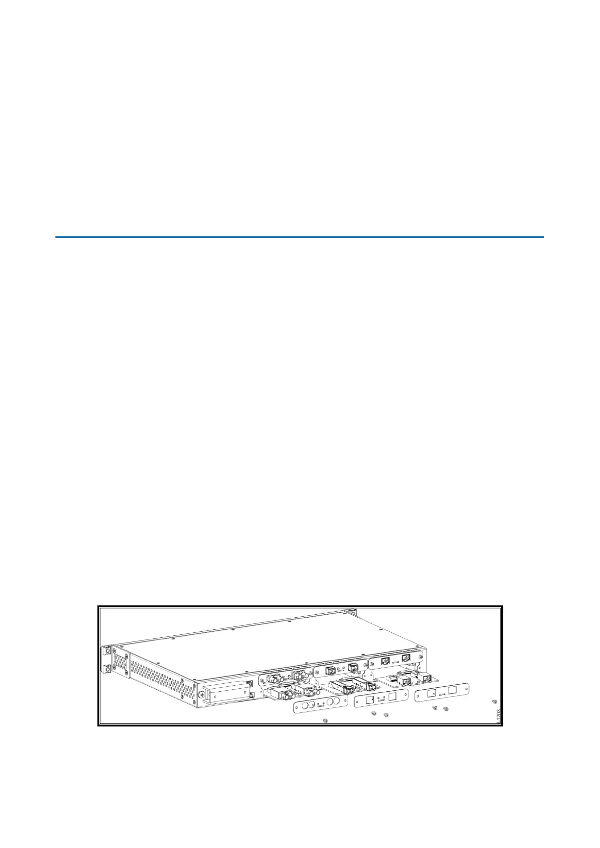
module. T1000 switches are built with a board and connector that allow it to be
changed in field without the need of taking the switch off the panel, as shown in the
figure below. The communication module of S2020 and S2024G are connected to the
main processor module, as these switches don’t allow the user to change its
communication modules
Figure 1: T1000 Communication modules
 Loading...