Home
GE
Medical Equipment
Venue Go
GE Venue Go Service Manual
4
of 1
of 1 rating
324 pages
Give review
Manual
Specs
To Next Page
To Next Page
To Previous Page
To Previous Page
Loading...
D
IRECTION
5813707-10
0, R
EVISION
2
V
ENUE
G
O
™ S
ERVICE
M
ANUAL
3-32
Chapter 3 - Syst
em Setup
PRELIMINARY
3-6-3
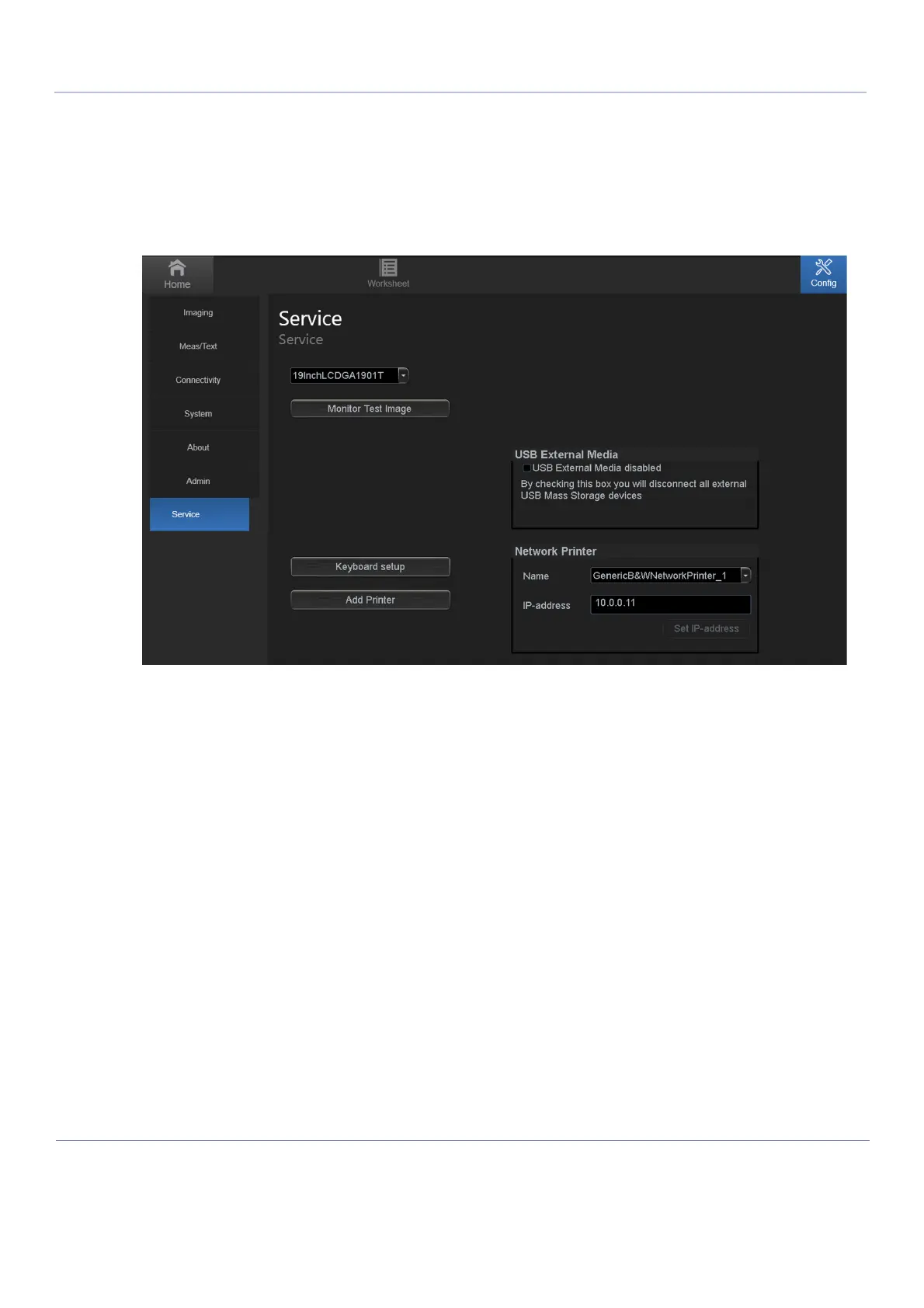
Service Screen Setup
3-6-3-1
Open Service Screen
1)
Log on as adm.
2)
From the Config side menu, select Service to view the Service
Screen.
Figure
3-22 Service Screen
105
107
Table of Contents
Table of Contents
3
Overview
27
Purpose of Chapter 1
27
Service Manual Overview
28
Contents in this Service Manual
28
Venue Go™ Models Covered in this Manual
29
Product Description
30
Important Conventions
32
Conventions Used in this Manual
32
Standard Hazard Icons
33
Safety Considerations
35
Introduction
35
Human Safety
35
Mechanical Safety
38
Electrical Safety
40
Venue Go™ Battery Safety
43
Patient Data Safety
43
Dangerous Procedure Warnings
44
Lockout/Tagout (LOTO) Requirements
45
Product Labels and Icons
46
Universal Product Labels
46
Label Descriptions
47
Venue Go™ Cart Labels Location
52
Returning/Shipping Probes and Repair Parts
53
EMC, EMI, and ESD
54
Electromagnetic Compatibility (EMC)
54
Peripherals Used in the Patient Environment
54
Compliance
55
Electrostatic Discharge (ESD) Prevention
56
General Caution
56
Direction 5813707-100, Revision
57
Contact Information
57
Customer Assistance
57
Overview
59
Purpose of Chapter 2
59
Console Requirements
60
Unit Environmental Requirements
60
Cooling Requirements
60
Lighting Requirements
60
Time and Manpower Requirements
60
Electrical Requirements
61
EMI Limitations
62
EMI Prevention/Abatement
63
Probe Environmental Requirements
63
Time and Manpower Requirements
64
Facility Needs
65
Purchaser Responsibilities
65
Required Facility Needs
66
Networking Pre-Installation Requirements
70
Connectivity Installation Worksheet
71
Overview
75
Purpose of Chapter 3
75
Setup Reminders
76
Average Setup Time
76
Setup Warnings
76
Safety Reminders
77
Receiving and Unpacking the Equipment
78
Warnings for Receiving and Unpacking the Equipment
78
Overview
78
Unpacking Venue Go™ System
79
Unpacking Venue Go™ Cart
81
Physical Inspection
84
EMI Protection
84
Preparing for Setup
85
Verifying Customer Order
85
Physical Inspection
85
Component Inspection
85
Irection Revision Enue Ervice Anual
86
Completing the Setup
89
System Specifications
89
Electrical Specifications
90
Connections on the I/O Rear Panel
90
Connecting Probes
90
Power On/Boot up
93
Power Shut down
93
Complete Power down
93
Configuration
94
Purpose of this Section
94
Venue Go™ Configuration
94
Service Screen Setup
106
Optional Peripherals/Peripheral Connection
107
Software Options Configuration
110
Connectivity Overview
111
Physical Connection
111
Stand-Alone Venue Go
111
Wired Ethernet from Venue Go™ to a Workstation
111
Connectivity Setup
112
Introduction
112
Select TCP/IP Screen
113
Changing the AE Title And/Or Port Number (Port No.)
114
Setup Connection to a DICOM Server
114
Options Setup
129
Software Options
129
USB Flash Card Setup
129
Paperwork after Setup
130
Installation Acceptance Test Criteria
130
User's Manual(S)
130
Product Locator Installation Card
130
Overview
139
Purpose of Chapter 4
139
General Procedures
140
Overview
140
Power On/Boot-Up
141
Power Shutdown
143
Logging on to the Venue Go™ as "ADM
143
Data Management
144
Deleting Patient Information
145
Transporting the Venue Go™ Ultrasound Scanner
146
Functional and Safety Checks
147
Overview
147
Safety Checks
148
Phantoms Performance Checks
148
Image Quality Tests
149
Probe/Connectors Check
155
Peripheral Checks
156
Mechanical Functions Checks
160
Functionality Tests
165
Overview
166
Purpose of Chapter 5
166
General Information
167
Introduction
167
Venue Go™ Mechanical Design
167
5813707-100, Revision
167
Venue Go™ System Design
169
External Power Supply Section
170
Venue Go™ User Interface Components
170
Venue Go™ Back End (C-BEB)
172
Back End
172
Compact Front End Board (C-FEB)
173
General Information
173
C-FEB Interfaces
173
Probe Selection Board (C-PSB)
175
Venue Go™ Display
176
General
176
Display Panel and Multi-Touch (MT)
176
Speaker
178
External Input/Output
179
System Power Distribution
180
Introduction
180
System Monitoring
181
Power Management Controller
182
System Power Consumption
182
Rechargeable Battery Pack
182
Cooling System
185
General Information
185
Peripherals
186
Internal Peripheral
186
External Peripherals
186
Purpose of this Section
187
5813707-100, Revision
187
Connectivity
187
Venue Go™ and a DICOM Server in a Network
187
Insite Exc
188
Introduction
188
Insite Exc Icon
188
Initiating a Request for Service (RFS)
190
Purpose of Chapter 6
193
Service Safety Considerations
195
Gathering Troubleshooting Data
196
Purpose of this Section
196
Collect Vital System Information
196
Collect a 'Trouble Image' with Logs
197
Noise Troubleshooting
199
Purpose of this Section
199
Introduction
199
Overview of Types of Noise
199
Different Power Outlet
201
Different System
201
Different Location
201
Disconnect External Cables
201
Irection Revision Enue Ervice Anual
201
Using a Loaner System During Faulty System Repair
202
Purpose of this Section
202
Transferring Data to the Loaner System
202
Overview
207
Purpose of Chapter 8
207
Internal Parts- Replacement Procedures
208
Preparations
208
Batteries Replacement Procedure
209
Back Cover Replacement Procedure
211
C-PSB Replacement Procedure
214
Probe Lever Replacement Procedure
216
Wifi Module Replacement Procedure
219
Fan Replacement Procedure
222
C-BEB and SSD Replacement Procedure
226
C-FEB Heat Sync Assembly Replacement Procedure
231
C-FEB Replacement Procedure
234
Front Display Assembly Replacement Procedure
237
Speakers Replacement Procedure
239
Cart bin Replacement Procedure
242
Mounting / Dismounting System on Cart
243
Cradle Assembly Replacement Procedure
246
Cradle Tilt Replacement Procedure
248
Casters Replacement Procedure
251
Printer Assembly Replacement Procedure
252
Printer and Printer Bracket Replacement Procedure
254
Cart Tray Replacement Procedure
256
Cart Up/Down Handle Replacement Procedure
259
ECG Replacement Procedure
260
Printer USB Cable Replacement Procedure
262
ECG USB Cable Replacement Procedure
264
AC/DC PSU and Split Cable Replacement Procedure
266
Software Loading Procedures
270
Software Installation/Update Procedures - General Overview
270
Preparation and Notes for Software Upgrade Procedure
271
Software Installation Procedure
272
Software Reload/Update Procedure
277
Software Recovery Procedure
284
Functional Checks to be Performed after Replacement Procedures
288
General Overview
288
Submitting a Replacement Procedure Report
288
Functional Checks Required Per Replacement Part Category
288
Overview
291
List of Abbreviations
292
Venue-Go™ System on Cart Overview
293
Renewal Parts Lists and Diagrams
294
Mechanical Hardware Parts
294
Covers
295
System Parts
295
Cart Parts
298
Probes
300
Software Media
301
System Power Cables
302
Peripherals
304
Overview
306
Periodic Maintenance Inspections
306
Warnings
307
Why Perform Maintenance Procedures
308
Keeping Records
308
Quality Assurance
308
Maintenance Task Schedule
308
Tools Required
310
Tools Required for Servicing the Venue Go
310
System Maintenance
311
Preliminary Checks
311
Functional Checks
312
Physical Inspection
314
Cleaning
315
Probe Maintenance
317
Probe Related Checks
317
Probe Handling
317
Basic Probe Care
317
Probe Cleaning
318
Returning and Shipping of Defective Probes
319
Electrical Safety Tests
320
Overview
320
Outlet Test - Wiring Arrangement - USA and Canada
322
Grounding Continuity
322
4
Based on 1 rating
Ask a question
Give review
Questions and Answers:
Need help?
Do you have a question about the GE Venue Go and is the answer not in the manual?
Ask a question
GE Venue Go Specifications
General
Brand
GE
Model
Venue Go
Category
Medical Equipment
Language
English
Related product manuals
GE Venue 50
289 pages
GE Venue R1
478 pages
GE Venue R2
478 pages
GE Venue Fit
300 pages
GE LOGIQ e Vet
127 pages
GE LOGIQ S8 Vet
418 pages
GE LOGIQ P3 VET
348 pages
GE Versana Balance
431 pages
GE Versana Essential
305 pages
GE Vivid E9
802 pages
GE LOGIQ V2
317 pages
GE Vivid S6
690 pages

 Loading...


