GE H
EALTHCARE
D
IRECTION
GA091568, R
EVISION
5 VIVID E9 S
ERVICE
M
ANUAL
8 - 120 Section 8-6 - Top Console Parts Replacement
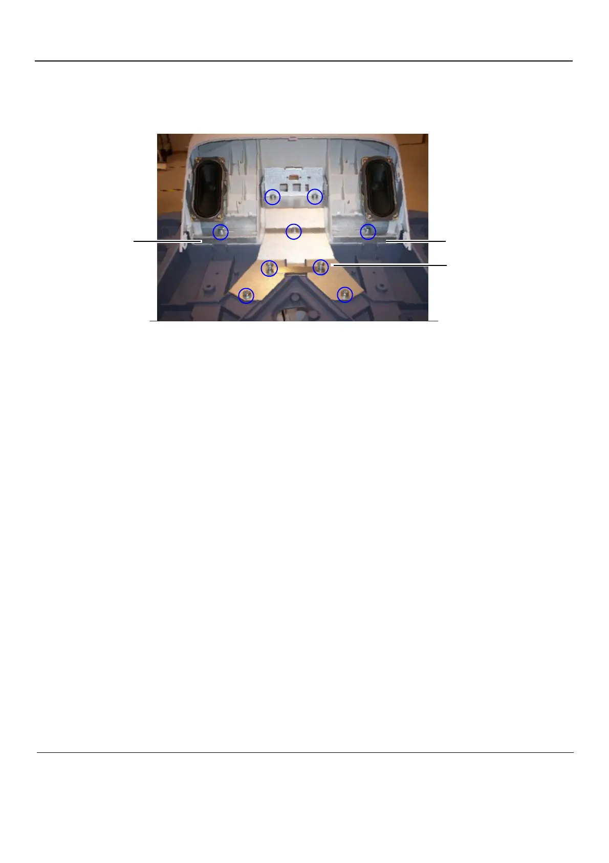
8-6-13-2 Remove the Frame UI Upper
The Bulkhead Plate is used to secure the Upper UI Frame to the Lower UI Frame.
1.) Remove the eleven fixing screws (see: Figure 8-134 "Bulkhead Plate and Plate Washer Frame" on
page 8-120).
2.) Remove the Bulkhead Plate and the Cable Clamp.
3.) Remove the Frame UI Upper.
8-6-13-3 Install the Frame UI Upper
1.) Position the Frame UI Upper so it aligns with the holes for the fixing screws.
2.) Position the Bulkhead Plate so it aligns with the holes for the fixing screws.
3.) Install the seven fixing screws as described below:
- The two upper screws are M6 x 20, Torque: 8.5 Nm.
- The next screw is M6 x 45, Torque: 8.5 Nm.
- The lower, left-most screw is M6 x 30, Torque 8,5 Nm. It is also used for a ground wire (not
illustrated).
- The three remaining lower screws are M6 x 25, Torque: 8.5 Nm. Two of the screws are also
fixing the Cable Clamp (see: Figure 8-170 "The Bulkhead Plate" on page 8-161).
4.) Install the Operator Panel, Lower.
5.) Install the Bulkhead Board.
6.) Install the two Speaker assemblies.
7.) Install the Operator Panel, Upper.
8.) Install the Operator Panel Knobs.
Figure 8-134 Bulkhead Plate and Plate Washer Frame
Plate Washer Frame
Bulkhead Plate
Plate Washer Frame

 Loading...


