112 ADV200 • Functions description and parameters list
22.2 – FUNCTIONS/DROOP
The Droop function is only active in Regulation mode = Flux vector OL or Flux vector CL.
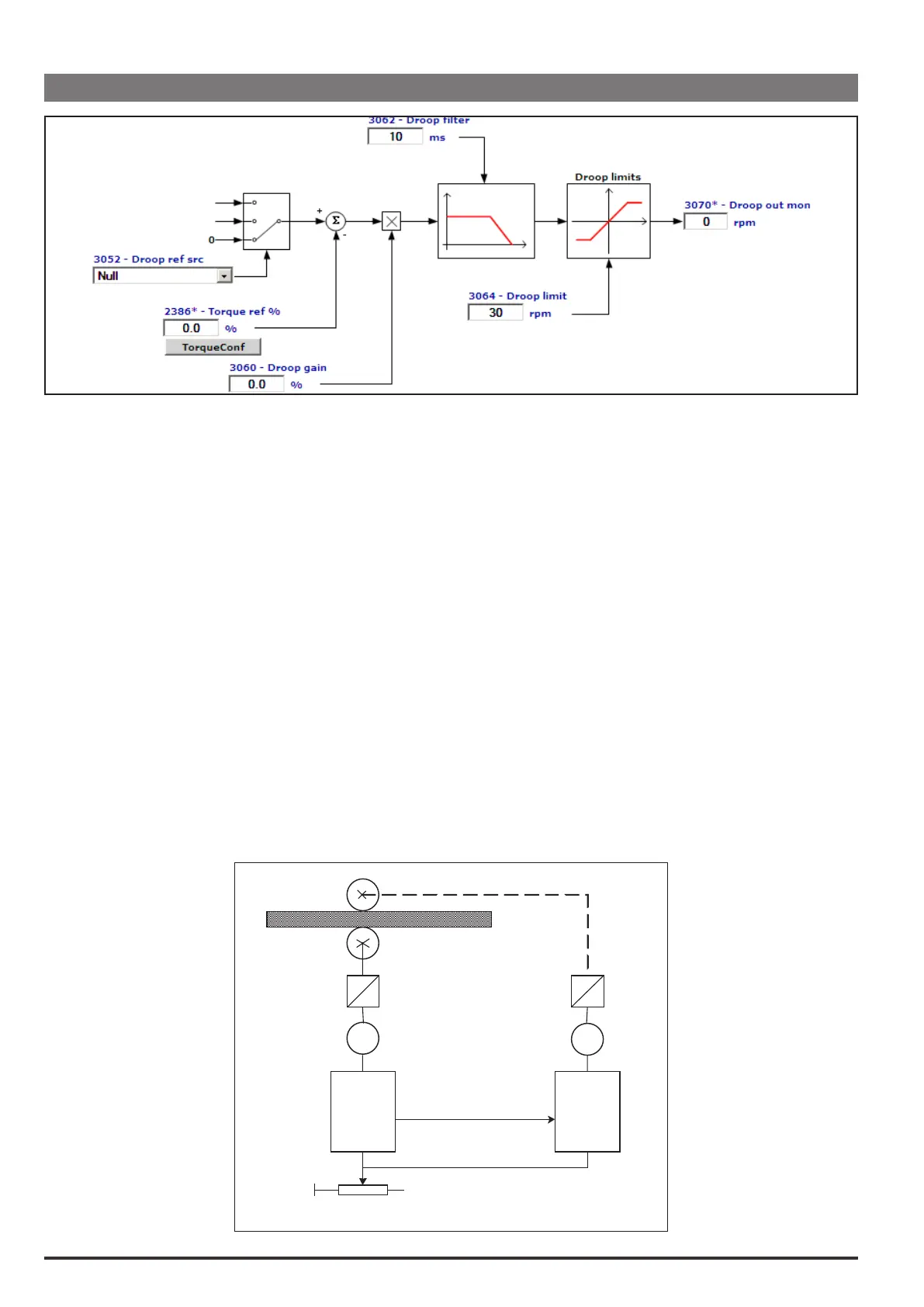
The block consists of:
- a node of comparison between Droop ref src connected to the Analog inp of the master drive torque reference
(set Torque ref nolter on the master analog output) and slave drive torque reference (Torque ref nolter produced
by the speed regulator).
- a proportional regulator the output of which is added to or subtracted from the reference of the slave drive speed
regulator. Set Speed ref 1 src equal to Droop out mon.
Before it is applied to the reference of the slave drive speed regulator, the adjustment passes through a low-pass lter
and a limit.
The Droop function is used to control two coupled motors.
The advantage of using the Droop block is that the speed regulator can remain enabled on both drives. If using the
Droop function, it can be adjusted to avoid speed regulator saturation on one of the two drives. Should there be a loss
of load by one of the two drives, the adjustment provided by the Droop block is limited by the dedicated parameter.
This function is used to scale the current. This block is typically used when two motors are coupled mechanically to
one another (for example if they are connected to the same shaft). They must turn at the same speed. If one of the two
motors tends to turn faster, the result is a difference in the load conditions which leads to an Overload condition. The
second motor acts as a brake. This causes a current unbalance, which can be eliminated by using the Droop function.
An adjustment is added to or subtracted from the reference of the slave drive speed regulator (proportional to the load
difference) to re-balance the two currents.
Example of machine on which the droop function can be used.
M1
DRIVE
MASTER
+
M2
DRIVE
SLAVE
Analog
output
Analog
input
LINE SPEED