ADV200 • Appendix 297
APPENDIX 1.
APP. 1.1 - Use of analog and digital I/Os from the MDPLC programming environment
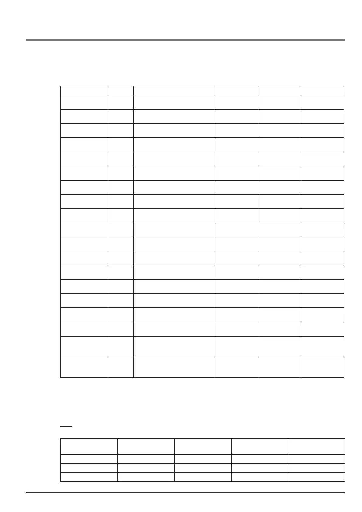
• The following table shows the internal and variable system parameters for External digital input exp.
DIGITAL INPUT EXP
Name Type Description Unit R/W
sysEDIBitWord DWORD Exp Digital input word
Scheme: “Digital Inputs”
Null 1200 R
sysEDIBitWordBit0 BOOL Exp Digital input 0 (0..1)
Scheme: “Digital Inputs”
Null 1210 R
sysEDIBitWordBit1 BOOL Exp Digital input 1 (0..1)
Scheme: “Digital Inputs”
Null 1212 R
sysEDIBitWordBit2 BOOL Exp Digital input 2 (0..1)
Scheme: “Digital Inputs”
Null 1214 R
sysEDIBitWordBit3 BOOL Exp Digital input 3 (0..1)
Scheme: “Digital Inputs”
Null 1216 R
sysEDIBitWordBit4 BOOL Exp Digital input 4 (0..1)
Scheme: “Digital Inputs”
Null 1218 R
sysEDIBitWordBit5 BOOL Exp Digital input 5 (0..1)
Scheme: “Digital Inputs”
Null 1220 R
sysEDIBitWordBit6 BOOL Exp Digital input 6 (0..1)
Scheme: “Digital Inputs”
Null 1222 R
sysEDIBitWordBit7 BOOL Exp Digital input 7 (0..1)
Scheme: “Digital Inputs”
Null 1224 R
SysEDIBitWordBit8 BOOL Exp Digital input 8 (0..1)
Scheme: “Digital Inputs”
Null 5510 R
SysEDIBitWordBit9 BOOL Exp Digital input 9 (0..1)
Scheme: “Digital Inputs”
Null 5512 R
SysEDIBitWordBit10 BOOL Exp Digital input 10 (0..1)
Scheme: “Digital Inputs”
Null 5514 R
SysEDIBitWordBit11 BOOL Exp Digital input 11 (0..1)
Scheme: “Digital Inputs”
Null 5516 R
SysEDIBitWordBit12 BOOL Exp Digital input 12 (0..1)
Scheme: “Digital Inputs”
Null 5518 R
SysEDIBitWordBit13 BOOL Exp Digital input 13 (0..1)
Scheme: “Digital Inputs”
Null 5520 R
SysEDIBitWordBit14 BOOL Exp Digital input 14 (0..1)
Scheme: “Digital Inputs”
Null 5522 R
SysEDIBitWordBit15 BOOL Exp Digital input 15 (0..1)
Scheme: “Digital Inputs”
Null 5524 R
sysExtIODigIn0 DWORD External expansion digital input 0
This parameter displays the state of
external inputs from 0 to 31
Null 5400 R
sysExtIODigIn1 DWORD External expansion digital input 1
This parameter displays the state of
external inputs from 32 to 63
Null 5402 R
• The following table shows the internal and variable system parameters for External analog input exp.
Analog input modules can have a resolution of 12 to 16 bits and scaling may vary from manufacturer to manu-
facturer.
E.g.:
12-bit module
Signal connected
Module configuration
Variant 1 Variant 2 Variant 3 Variant 4
-10V..+10V -2048..+2047 -32768..+32767 -16384..+16383
0V..+10V 0..+4095 0..+2047 0..+32767 0..+65535
4..20mA 0..+32767 +6553..+32767 +3276..+16383
 Loading...


