ADV200 • Functions description and parameters list 9
Note ! The drive is factory-set to control Asynchronous motors. To switch to Synchronous mode, send the Load synch control com-
mand (In menu 4 DRIVE CONFIG, first set PAR 554 Access mode = Expert, then again in menu 4 - DRIVE CONFIG, run parameter
6100 Load synch control). The drive is re-started (in this mode, reference should be made to the “ADV 200 – Field-oriented vec-
tor inverter for synchronous motors – Description of functions and list of parameters” guide on the CD supplied with the inverter
or downloadable from the www.gefran.com website).
To return to Asynchronous motor control mode, send the Load asynch control command (PAR 6100). The drive is re-started to
operate in the new mode.
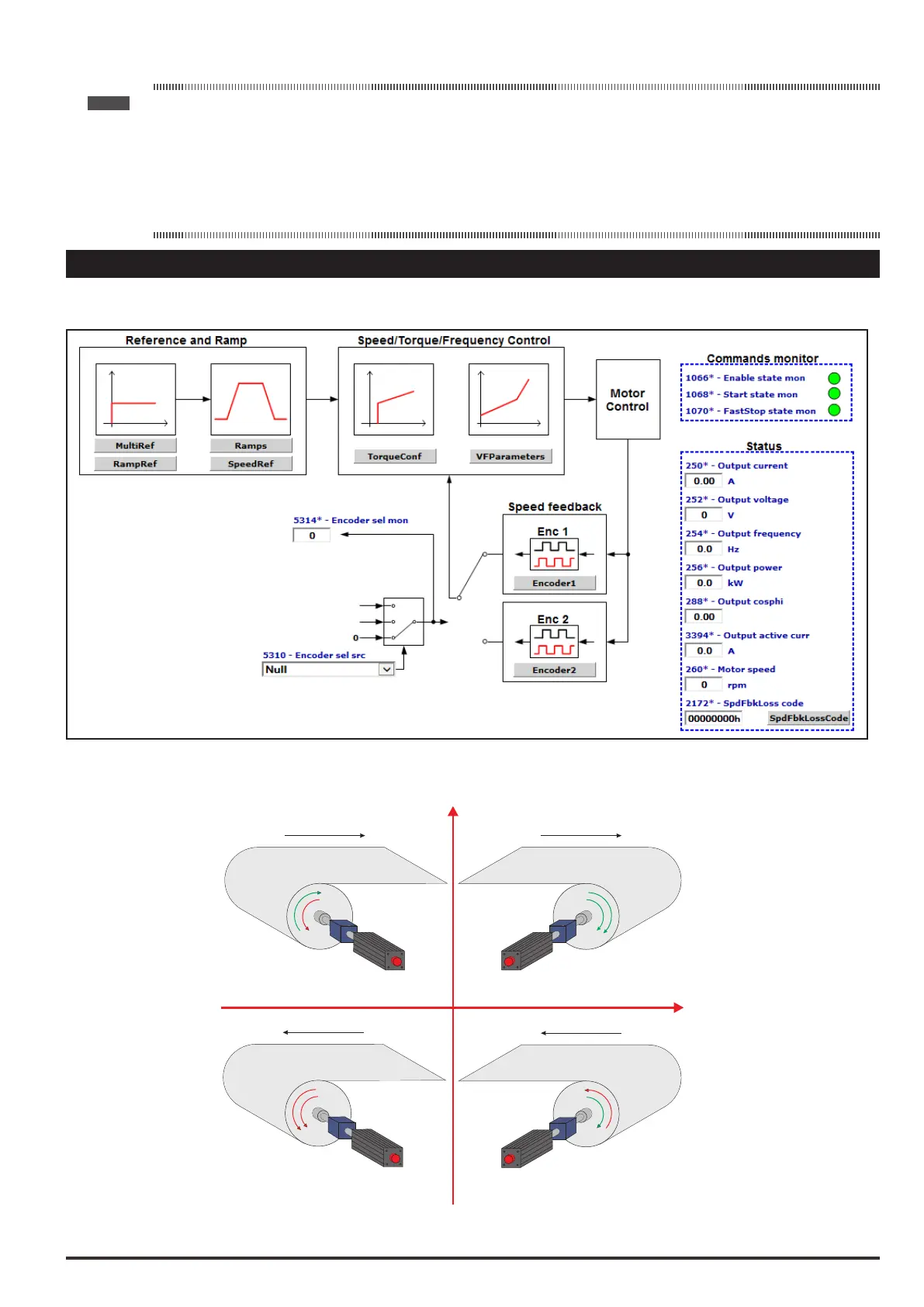
1 – MONITOR
The monitor menu displays the measured values of the sizes and of the drive operating parameters.
Relationship between Speed-Torque-Power monitor parameters
T
Line Direction
T
Line Direction
T
IPA 260 Motor speed = Positive
IPA 284 Torque current = Positive
IPA 3354 Output active curr = Positive
IPA 256 Output power = Positive
IPA 260 Motor speed = Negative
IPA 284 Torque current = Negative
IPA 3354 Output active curr = Positive
IPA 256 Output power = Positive
IPA 260 Motor speed = Negative
IPA 284 Torque current = Positive
IPA 3354 Output active curr = Negative
IPA 256 Output power = Negative
IPA 260 Motor speed = Positive
IPA 284 Torque current = Negative
IPA 3354 Output active curr = Negative
IPA 256 Output power = Negative
Line Direction
Motor FWD
Motor REV
Brake FWD
Brake REV
T
Line Direction
Speed
Torque
I
II
III
IV
 Loading...


