ADV200 • Functions description and parameters list 25
5 – REFERENCES
ADV drives are provided with a speed regulation circuit, which can be adapted to suit the various applications. In the
standard version, the regulator has PI behaviour and the regulator parameters are the same for the entire eld of regu-
lation.
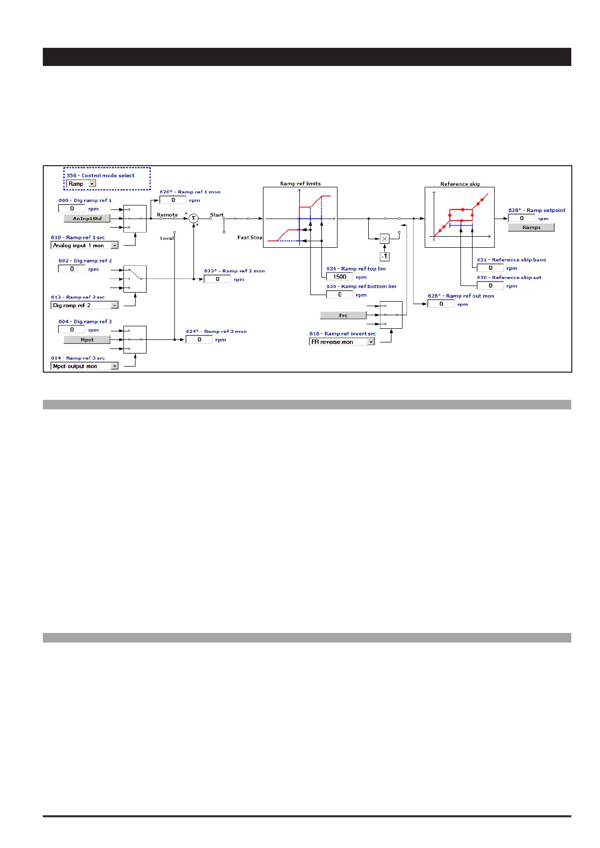
Different sources can be used for the speed and torque references, depending on how the 554 Control mode select
parameter is set.
Menu PAR Description UM Type FB BIT Def Min Max Acc Mod
5.1 600 Dig ramp ref 1 FF INT16 16/32 0 CALCI CALCI RW FVS
Setting of the digital ramp reference. The speed that the drive must reach after completing the acceleration
phase is set with the ramp reference. Variations in the ramp reference are made with the selected ramp times.
The size of the ramp reference determines the motor speed value. The sign determines the direction of rota-
tion. The Ramp ref parameter also refers to a minimum speed, if set. When the “Motor potentiometer” or
“Multispeed” functions are selected the relative references are used. This reference can only be used in the
Remote mode.
The overall ramp reference is the result of the sum of the values with the Ramp ref 1 and Ramp ref 2 sign.
Example 1: Ramp ref 1 = + 500 rpm Ramp ref 2 = + 300 rpm
Ramp ref = 500 rpm + 300 rpm = 800 rpm
Example 2: Ramp ref 1 = + 400 rpm Ramp ref 2 = - 600 rpm
Ramp ref = 400 rpm – 600 rpm = - 200 rpm
Menu PAR Description UM Type FB BIT Def Min Max Acc Mod
5.2 602 Dig ramp ref 2 FF INT16 16/32 0 CALCI CALCI ERW FVS
Setting of the digital ramp reference. The speed that the drive must reach after completing the acceleration
phase is set with the ramp reference. Variations in the ramp reference are made with the selected ramp times.
The size of the ramp reference determines the motor speed value. The sign determines the direction of rota-
tion. The Ramp ref parameter also refers to a minimum speed, if set. When the “Motor potentiometer” or
“Multispeed” functions are selected the relative references are used.
In Remote mode the overall ramp reference is the result of the sum of the values with the Ramp ref 1 and
Ramp ref 2 sign.
Example 1: Ramp ref 1 = + 500 rpm Ramp ref 2 = + 300 rpm
Ramp ref = 500 rpm + 300 rpm = 800 rpm
 Loading...


