290 8 Programming: Cycles
8.6 SL cycles
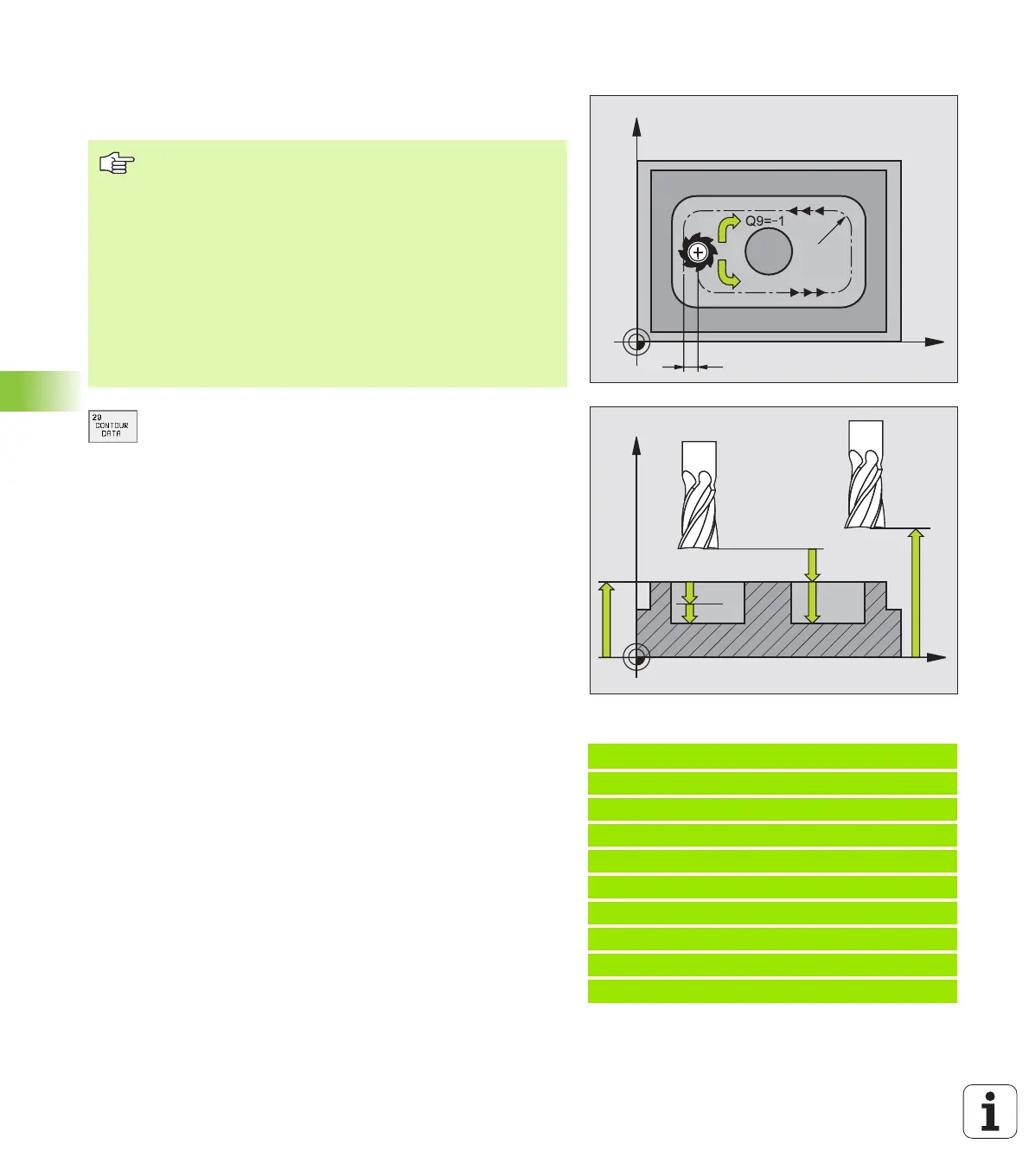
CONTOUR DATA (Cycle 20)
Machining data for the subprograms describing the subcontours are
entered in Cycle 20.
U Milling depth Q1 (incremental value): Distance
between workpiece surface and bottom of pocket
U Path overlap factor Q2: Q2 x tool radius = stepover
factor k
U Finishing allowance for side Q3 (incremental
value): Finishing allowance in the working plane
U Finishing allowance for floor Q4 (incremental
value): Finishing allowance in the tool axis
U Workpiece surface coordinate Q5 (absolute value):
Absolute coordinate of the workpiece surface
U Set-up clearance Q6 (incremental value): Distance
between tool tip and workpiece surface
U Clearance height Q7 (absolute value): Absolute
height at which the tool cannot collide with the
workpiece (for intermediate positioning and retraction
at the end of the cycle)
U Inside corner radius Q8: Inside “corner” rounding
radius; entered value is referenced to the tool
midpoint path.
U Direction of rotation ? Clockwise = -1 Q9:
Machining direction for pockets
n Clockwise (Q9 = –1 up-cut milling for pocket and
island)
n Counterclockwise (Q9 = +1 climb milling for pocket
and island)
You can check the machining parameters during a program
interruption and overwrite them if required.
Example: NC blocks
57 CYCL DEF 20.0 CONTOUR DATA
Q1=-20 ;MILLING DEPTH
Q2=1 ;TOOL PATH OVERLAP
Q3=+0.2 ;ALLOWANCE FOR SIDE
Q4=+0.1 ;ALLOWANCE FOR FLOOR
Q5=+30 ;SURFACE COORDINATE
Q6=2 ;SET-UP CLEARANCE
Q7=+80 ;CLEARANCE HEIGHT
Q8=0.5 ;ROUNDING RADIUS
Q9=+1 ;DIRECTION OF ROTATION
X
Y
k
Q9=+1
Q8
X
Z
Q6
Q7
Q1
Q10
Q5
Before programming, note the following:
Cycle 20 is DEF active which means that it becomes
effective as soon as it is defined in the part program.
The algebraic sign for the cycle parameter DEPTH
determines the working direction. If you program depth =
0, the TNC does not execute that next cycle.
The machining data entered in Cycle 20 are valid for Cycles
21 to 24.
If you are using the SL cycles in Q parameter programs,
the cycle parameters Q1 to Q19 cannot be used as
program parameters.
 Loading...


