HEIDENHAIN TNC 426, TNC 430 343
9.2 Subprograms
9.2 Subprograms
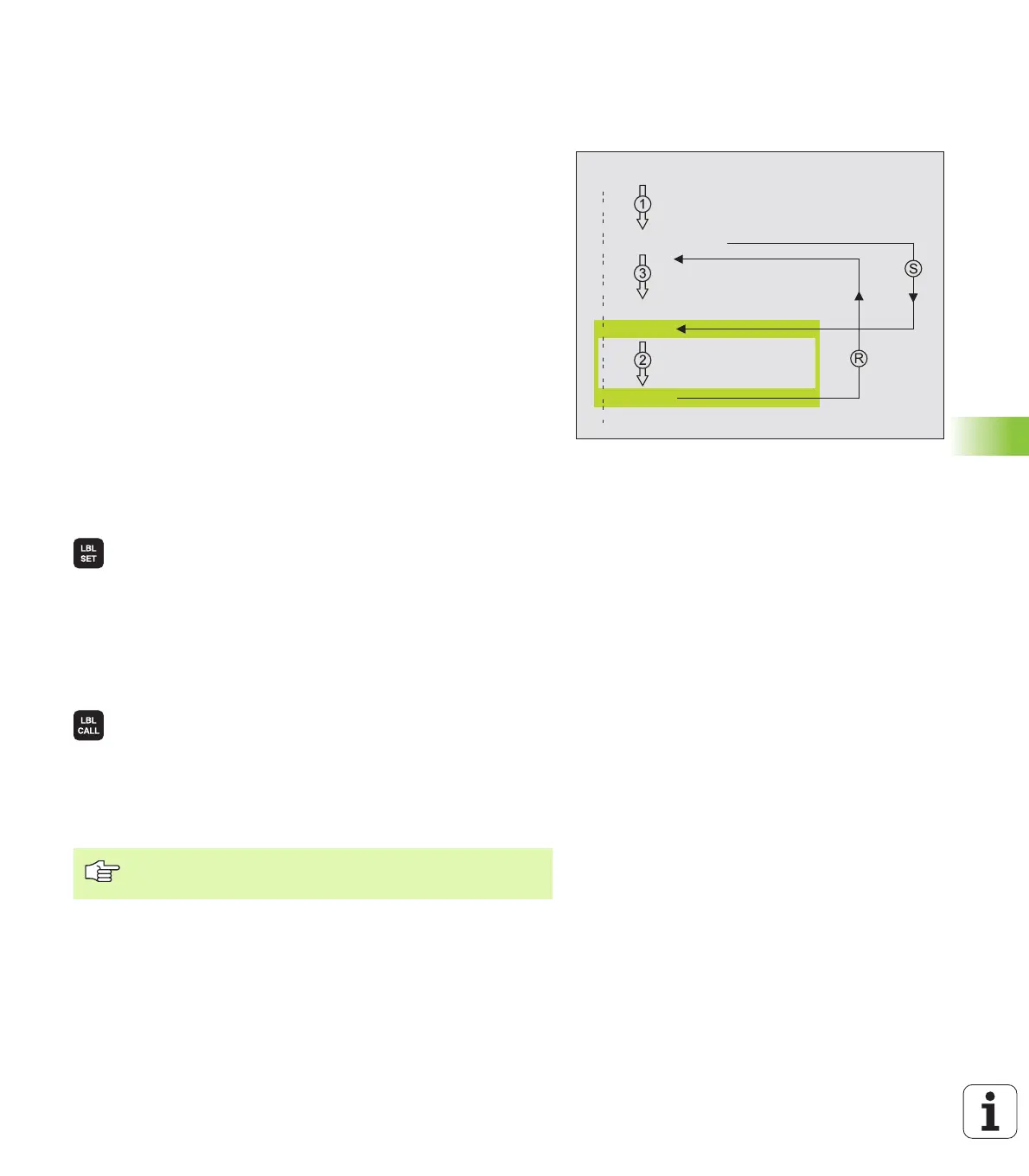
Operating sequence
1 The TNC executes the part program up to the block in which a
subprogram is called with CALL LBL.
2 The subprogram is then executed from beginning to end. The
subprogram end is marked LBL 0.
3 The TNC then resumes the part program from the block after the
subprogram call.
Programming notes
n A main program can contain up to 254 subprograms.
n You can call subprograms in any sequence and as often as desired.
n A subprogram cannot call itself.
n Write subprograms at the end of the main program (behind the block
with M2 or M30).
n If subprograms are located before the block with M02 or M30, they
will be executed at least once even if they are not called.
Programming a subprogram
U To mark the beginning, press the LBL SET key and
enter a label number.
U Enter the subprogram number.
U To mark the end, press the LBL SET key and enter the
label number “0”.
Calling a subprogram
U To call a subprogram, press the LBL CALL key.
U Label number: Enter the label number of the
subprogram you wish to call.
U Repeat REP: Ignore the dialog question with the NO
ENT key. Repeat REP is used only for program section
repeats.
0 BEGIN PGM ...
CALL LBL1
L Z+100 M2
LBL1
LBL0
END PGM ...
CALL LBL 0 is not permitted (label 0 is only used to mark
the end of a subprogram).
 Loading...


