HEIDENHAIN TNC 426, TNC 430 297
8.6 SL cycles
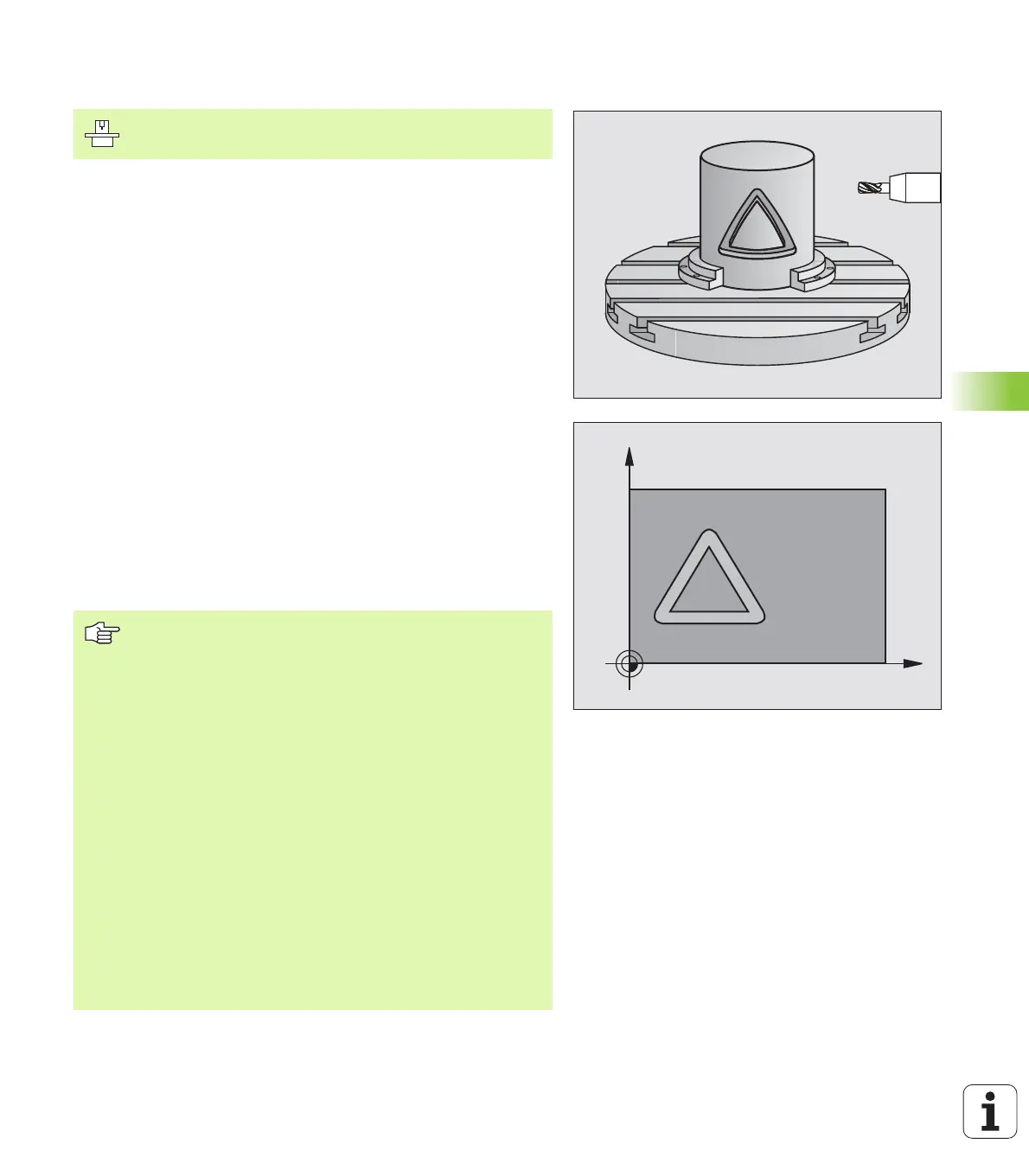
CYLINDER SURFACE (Cycle 27)
This cycle enables you to program a contour in two dimensions and
then roll it onto a cylindrical surface for 3-D machining. Use Cycle 28 if
you wish to mill guide notches onto the cylinder surface.
The contour is described in a subprogram identified in Cycle 14
CONTOUR GEOMETRY.
The subprogram contains coordinates in a rotary axis and in its parallel
axis. The rotary axis C, for example, is parallel to the Z axis. The path
functions L, CHF, CR, RND APPR (except APPR LCT) and DEP are
available.
The dimensions in the rotary axis can be entered as desired either in
degrees or in mm (or inches). You can select the desired dimension
type in the cycle definition.
1 The TNC positions the tool over the cutter infeed point, taking the
allowance for side into account.
2 At the first plunging depth, the tool mills along the programmed
contour at the milling feed rate Q12.
3 At the end of the contour, the TNC returns the tool to the setup
clearance and returns to the point of penetration;
4 Steps 1 to 3 are repeated until the programmed milling depth Q1
is reached.
5 Then the tool moves to the setup clearance.
C
Z
Machine and control must be specially prepared by the
machine tool builder for use of this cycle.
Before programming, note the following:
The memory capacity for programming an SL cycle is
limited. For example, you can program up to 256 straight-
line blocks in one SL cycle.
The algebraic sign for the cycle parameter DEPTH
determines the working direction. If you program DEPTH
= 0, the cycle will not be executed.
This cycle requires a center-cut end mill (ISO 1641).
The cylinder must be set up centered on the rotary table.
The tool axis must be perpendicular to the rotary table. If
this is not the case, the TNC will generate an error
message.
This cycle can also be used in a tilted working plane.
The TNC checks whether the compensated and non-
compensated tool paths lie within the display range of the
rotary axis, which is defined in Machine Parameter 810.x.
If the error message “Contour programming error” is
output, set MP 810.x = 0.