Table 3-2 describes the buzzer switch.
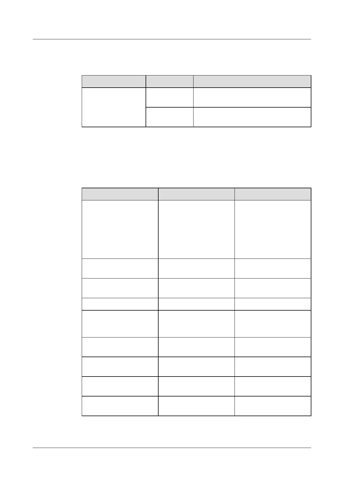
Table 3-2 Buzzer switch
Item Status Description
Buzzer switch ON The communication between the monitoring
unit and the host is normal
OFF The communication between the monitoring
unit and the host is faulty
Terminal Block
Table 3-3 describes the terminal blocks of the H303ESC EMU.
Table 3-3 Terminal blocks of the H303ESC EMU
Silk Screen Function Remarks
JTD1-JTD16 Socket for the standby
Boolean value input
l Used to monitor the PDU
status, fan tray status, and
other Boolean values
l Connected to the
monitored devices
according to the
application scenarios
JTD17-JTD20
Socket for the -48 V
detection signal input
Connected to the detected -48
V power
JAC1 Socket for the first optical
coupling control output
Connected to the port on the
controlled device
JAC2 Relay output (reserved) Unavailable
JAK1 and JAK2 Socket for the external alarm
device
Connected to the alarm
components, such as the row
and column alarm LEDs
JAK4 Socket for the dry contact
output
Connected to the port on the
controlled device
JTM1 Socket for the door-status
sensor
Connected to the door-status
sensor
JAB1 Socket for the buzzer Connected to the buzzer on
the cabinet
JTP1 Socket for the MDF sensor Connected to the alarm unit
on the MDF
UA5000 Universal Access Unit
Environment Monitoring 3 H303ESC Monitoring Solution
Issue 01 (2012-08-17) Huawei Proprietary and Confidential
Copyright © Huawei Technologies Co., Ltd.
8
 Loading...